In this article we are going to examine an older but still highly useful integrated circuit – the 4047 Astable/Monostable multivibrator:

Our reason for doing this is to demonstrate another way to create a square-wave output for digital circuits (astable mode) and also generate single pulses (monostable mode).
Sometimes one can get carried away with using a microcontroller by default – and forget that there often can be simpler and much cheaper ways of doing things. And finally, the two can often work together to solve a problem.
What is a multivibrator? In electronics terms this means more than one vibrator. It creates an electrical signal that changes state on a regular basis (astable) or on demand (monostable).
You may recall creating monostable and astable timers using the 555 timer described in an earlier article. One of the benefits of the 4047 is being able to do so as well, but with fewer external components. Here is the pinout diagram for a 4047 (from the Fairchild data sheet):


Note that there are three outputs, Q, Q and OSC out. Q is the normal output, Q is the inverse of Q – that is if Q is high, Q is low – at the same frequency. OSC output provides a signal that is very close to twice the frequency of Q. We will consider the other pins as we go along. In the following small video, we have LEDs connected to all three outputs – you can see how Q and Q alternate, and the increased frequency of OSC out:
That was an example of the astable mode. The circuit used is shown below. The only drawback of using a 4047 is that you cannot alter the duty cycle of your astable output – it will always be 50% high and 50% low. The oscillator output is not guaranteed to have a 50% duty cycle, but comes close. The time period (and therefore the frequency) is determined by two components – R1 and the capacitor:
[Quick update – in the schematic below, also connect 4047 pin 14 to +5V]

The values for R2~R4 are 560 ohms, for the LEDs. R1 and the capacitor form an RC circuit, which controls the oscillation frequency. How can we calculate the frequency? The data sheet tells us that time (period of time the oscillator is ‘high’) is equal to 4.4 multiplied by the value of R1 and the capacitor. As the duty cycle is always 50%, we double this value, then divide the result into one. In other words:

 And as the frequency from the OSC out pin is twice that of Q or
 Q, the formula for the OSC out frequency is:


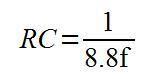
However the most useful formula would allow you to work with the values of R and C to use for a desired frequency f:

When calculating your values, remember that you need to work with whole units, such as Farads and Ohms- not microfarads, mega-ohms, etc. This chart of SI prefixes may be useful for conversions.
The only thing to take note of is the tolerance of your resistor and capacitor. If you require a certain, exact frequency try to use some low-tolerance capacitors, or replace the resistor with a trimpot of a value just over your required resistor value.
Then you can make adjustments and measure the result with a frequency counter. For example, when using a value of 0.1uF for C and 15 k ohm for R, the theoretical frequency is 151.51 Hz; however in practice this resulted with a frequency of 144.78 Hz.
Don’t forget that the duty cycle is not guaranteed to be 50% from the OSC out pin. This is shown in the following demonstration video. We measure the frequency from all three output pins, then measure the duty cycle from the same pins:
(The auto-ranging on that multimeter is somewhat annoying).
Now for some more more explanation about the 4047. You can activate the oscillations in two ways, via a high signal into pin 5 (pin 4 must then be low) or via a low signal into pin 4 (and pin 5 must be low). Setting pin 9 high will reset the oscillator, so Q is low and Q is high.
The monostable mode is also simple to create and activate. I have not made a video clip of monstable operation, as this would only comprise of staring at an LED. However, here is an example circuit with two buttons added, one to trigger the pulse (or start it), and another to reset the timer (cancel any pulse and start again):
[Quick update – in the schematic below, also connect 4047 pin 14 to +5V]

The following formula is used to calculate the duration of the pulse time:

 Where time is in seconds, R is Ohms, and C is Farads. Once again, the OSC output pin also has a modified output – it’s time period will be 1.2RC.
To conclude, the 4047 offers a simple and cheap way to generate a 50% duty cycle square wave or use as a monostable timer. You can order your 4047s from PMD Way with free delivery worldwide.
This post brought to you by pmdway.com – everything for makers and electronics enthusiasts, with free delivery worldwide.
To keep up to date with new posts at tronixstuff.com, please subscribe to the mailing list in the box on the right, or follow us on twitter @tronixstuff.

You must be logged in to post a comment.