Skip to content
tronixstuff.com
Search
Home
Projects
Arduino Tutorials
Electronics Tutorials
Kit Reviews
Books
About
Category:
tronixstuff
Tutorial – LM3914 Dot/Bar Display Driver IC
Tutorial – Ethernet Shields and Arduino
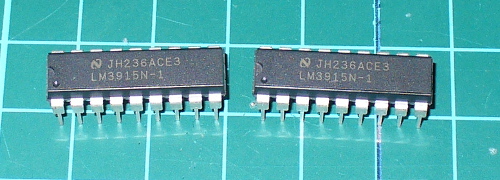
Tutorial – LM3915 Logarithmic Dot/Bar Display Driver IC
Tutorial – the Arduino AREF Pin
Tutorial – Numeric Keypads and Arduino
Tutorial – L298N Dual Motor Controller Modules and Arduino
Tutorial – Using DS1307 and DS3231 Real-time Clock Modules with Arduino
Tutorial – x (twitter) and Arduino
Tutorial – Reading RFID tags with Arduino
Tutorial – Arduino and the TLC5940 PWM LED Driver IC
Next Page
Subscribe
Subscribed
tronixstuff.com
Join 185 other subscribers
Sign me up
Already have a WordPress.com account?
Log in now.
tronixstuff.com
Subscribe
Subscribed
Sign up
Log in
Report this content
View site in Reader
Manage subscriptions
Collapse this bar