Skip to content
tronixstuff.com
Search
Home
Projects
Arduino Tutorials
Electronics Tutorials
Kit Reviews
Books
About
Author:
John Boxall
Tutorial – L298N Dual Motor Controller Modules and Arduino
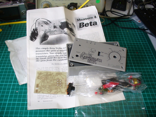
Old Kit Review – Silicon Chip Transistor Beta Tester
Arduino for Arduinians – 70 Projects for the Experienced Programmer
Learn Microchip AVR Programming with “AVR Workshop A Hands-On Introduction with 60 Projects”
Announcing Arduino IDE 2.0
Blinky the one-eyed Clock
Build a simple WFH Messaging System
Learn Arduino with “Arduino Workshop, 2nd Edition: A Hands-on Introduction with 65 Projects”
A tiny tiny 0.49″ 64 x 32 Graphic I2C OLED Display with Arduino
Tutorial – Using the 0.96″ 80 x 160 Full Color IPS LCD Module with Arduino
Previous Page
Next Page
Subscribe
Subscribed
tronixstuff.com
Join 186 other subscribers
Sign me up
Already have a WordPress.com account?
Log in now.
tronixstuff.com
Subscribe
Subscribed
Sign up
Log in
Report this content
View site in Reader
Manage subscriptions
Collapse this bar