Category Archives: part review

Tutorial – Arduino and the MAX7219 LED Display Driver IC

Sooner or later Arduino enthusiasts and beginners alike will come across the MAX7219 IC. And for good reason, it’s a simple and somewhat inexpensive method of controlling 64 LEDs in either matrix or numeric display form. Furthermore they can be chained together to control two or more units for even more LEDs. Overall – they’re a lot of fun and can also be quite useful, so let’s get started.

Here’s an example of a MAX7219 and another IC which is a functional equivalent, the AS1107 from Austria Microsystems. You might not see the AS1107 around much, but it can be cheaper – so don’t be afraid to use that instead:

MAX7219 LED driver IC from PMD Way

 At first glance you may think that it takes a lot of real estate, but it saves some as well. As mentioned earlier, the MAX7219 can completely control 64 individual LEDs – including maintaining equal brightness, and allowing you to adjust the brightness of the LEDs either with hardware or software (or both). It can refresh the LEDs at around 800 Hz, so no more flickering, uneven LED displays.

You can even switch the display off for power saving mode, and still send it data while it is off. And another good thing – when powered up, it keeps the LEDs off, so no wacky displays for the first seconds of operation. For more technical information, here is the data sheet: MAX7219.pdf. Now to put it to work for us – we’ll demonstrate using one or more 8 x 8 LED matrix displays, as well as 8 digits of 7-segment LED numbers.

Before continuing, download and install the LedControl Arduino library as it is essential for using the MAX7219.

Controlling LED matrix displays with the MAX7219

First of all, let’s examine the hardware side of things. Here is the pinout diagram for the MAX7219:

MAX7219 LED driver IC from PMD Way

The MAX7219 drives eight LEDs at a time, and by rapidly switching banks of eight your eyes don’t see the changes. Wiring up a matrix is very simple – if you have a common matrix with the following schematic:

MAX7219 LED driver IC from PMD Way


connect the MAX7219 pins labelled DP, A~F to the row pins respectively, and the MAX7219 pins labelled DIG0~7 to the column pins respectively. A total example circuit with the above matrix  is as follows:

MAX7219 LED driver IC from PMD Way

The circuit is quite straight forward, except we have a resistor between 5V and MAX7219 pin 18. The MAX7219 is a constant-current LED driver, and the value of the resistor is used to set the current flow to the LEDs. Have a look at table eleven on page eleven of the data sheet:

MAX7219 LED driver IC from PMD Way

You’ll need to know the voltage and forward current for your LED matrix or numeric display, then match the value on the table. E.g. if you have a 2V 20 mA LED, your resistor value will be 28kΩ (the values are in kΩ). Finally, the MAX7219 serial in, load and clock pins will go to Arduino digital pins which are specified in the sketch. We’ll get to that in the moment, but before that let’s return to the matrix modules.

In the last few months there has been a proliferation of inexpensive kits that contain a MAX7219 or equivalent, and an LED matrix. These are great for experimenting with and can save you a lot of work – some examples of which are shown below:

MAX7219 LED driver IC from PMD Way

Now for the sketch. You need the following two lines at the beginning of the sketch:

#include "LedControl.h" 
LedControl lc=LedControl(12,11,10,1);

The first pulls in the library, and the second line sets up an instance to control. The four parameters are as follows:

  1. the digital pin connected to pin 1 of the MAX7219 (“data in”)
  2. the digital pin connected to pin 13 of the MAX7219 (“CLK or clock”)
  3. the digital pin connected to pin 12 of the MAX7219 (“LOAD”)
  4. The number of MAX7219s connected.

If you have more than one MAX7219, connect the DOUT (“data out”) pin of the first MAX7219 to pin 1 of the second, and so on. However the CLK and LOAD pins are all connected in parallel and then back to the Arduino.

Next, two more vital functions that you’d normally put in void setup():

lc.shutdown(0,false);
lc.setIntensity(0,8);

The first line above turns the LEDs connected to the MAX7219 on. If you set TRUE, you can send data to the MAX7219 but the LEDs will stay off. The second line adjusts the brightness of the LEDs in sixteen stages. For both of those functions (and all others from the LedControl) the first parameter is the number of the MAX7219 connected. If you have one, the parameter is zero… for two MAX7219s, it’s 1 and so on.

Finally, to turn an individual LED in the matrix on or off, use:

lc.setLed(0,col,row,true);

which turns on an LED positioned at col, row connected to MAX7219 #1. Change TRUE to FALSE to turn it off. These functions are demonstrated in the following sketch:

#include "LedControl.h" //  need the library
LedControl lc=LedControl(12,11,10,1); // 

// pin 12 is connected to the MAX7219 pin 1
// pin 11 is connected to the CLK pin 13
// pin 10 is connected to LOAD pin 12
// 1 as we are only using 1 MAX7219

void setup()
{
  // the zero refers to the MAX7219 number, it is zero for 1 chip
  lc.shutdown(0,false);// turn off power saving, enables display
  lc.setIntensity(0,8);// sets brightness (0~15 possible values)
  lc.clearDisplay(0);// clear screen
}
void loop()
{
  for (int row=0; row<8; row++)
  {
    for (int col=0; col<8; col++)
    {
      lc.setLed(0,col,row,true); // turns on LED at col, row
      delay(25);
    }
  }

  for (int row=0; row<8; row++)
  {
    for (int col=0; col<8; col++)
    {
      lc.setLed(0,col,row,false); // turns off LED at col, row
      delay(25);
    }
  }
}

And a quick video of the results:

How about controlling two MAX7219s? Or more? The hardware modifications are easy – connect the serial data out pin from your first MAX7219 to the data in pin on the second (and so on), and the LOAD and CLOCK pins from the first MAX7219 connect to the second (and so on). You will of course still need the 5V, GND, resistor, capacitors etc. for the second and subsequent MAX7219.

You will also need to make a few changes in your sketch. The first is to tell it how many MAX7219s you’re using in the following line:

LedControl lc=LedControl(12,11,10,X);

by replacing X with the quantity. Then whenever you’re using  a MAX7219 function, replace the (previously used) zero with the number of the MAX7219 you wish to address. They are numbered from zero upwards, with the MAX7219 directly connected to the Arduino as unit zero, then one etc. To demonstrate this, we replicate the previous example but with two MAX7219s:

#include "LedControl.h" //  need the library
LedControl lc=LedControl(12,11,10,2); // 

// pin 12 is connected to the MAX7219 pin 1
// pin 11 is connected to the CLK pin 13
// pin 10 is connected to LOAD pin 12
// 1 as we are only using 1 MAX7219

void setup()
{
  lc.shutdown(0,false);// turn off power saving, enables display
  lc.setIntensity(0,8);// sets brightness (0~15 possible values)
  lc.clearDisplay(0);// clear screen

  lc.shutdown(1,false);// turn off power saving, enables display
  lc.setIntensity(1,8);// sets brightness (0~15 possible values)
  lc.clearDisplay(1);// clear screen
}

void loop()
{
  for (int row=0; row<8; row++)
  {
    for (int col=0; col<8; col++)
    {
      lc.setLed(0,col,row,true); // turns on LED at col, row
      lc.setLed(1,col,row,false); // turns on LED at col, row
      delay(25);
    }
  }

  for (int row=0; row<8; row++)
  {
    for (int col=0; col<8; col++)
    {
      lc.setLed(0,col,row,false); // turns off LED at col, row
      lc.setLed(1,col,row,true); // turns on LED at col, row      
      delay(25);
    }
  }
}

And again, a quick demonstration:

Another fun use of the MAX7219 and LED matrices is to display scrolling text. For the case of simplicity we’ll use the LedControl library and the two LED matrix modules from the previous examples.

First our example sketch – it is quite long however most of this is due to defining the characters for each letter of the alphabet and so on. We’ll explain it at the other end!

// based on an orginal sketch by Arduino forum member "danigom"
// http://forum.arduino.cc/index.php?action=profile;u=188950

#include <avr/pgmspace.h>
#include <LedControl.h>

const int numDevices = 2;      // number of MAX7219s used
const long scrollDelay = 75;   // adjust scrolling speed

unsigned long bufferLong [14] = {0}; 

LedControl lc=LedControl(12,11,10,numDevices);

prog_uchar scrollText[] PROGMEM ={
    "  THE QUICK BROWN FOX JUMPED OVER THE LAZY DOG 1234567890 the quick brown fox jumped over the lazy dog   "};

void setup(){
    for (int x=0; x<numDevices; x++){
        lc.shutdown(x,false);       //The MAX72XX is in power-saving mode on startup
        lc.setIntensity(x,8);       // Set the brightness to default value
        lc.clearDisplay(x);         // and clear the display
    }
}

void loop(){ 
    scrollMessage(scrollText);
    scrollFont();
}

///////////////////////////////////////////////////////////////////////////////////////////////////////////////////

prog_uchar font5x7 [] PROGMEM = {      //Numeric Font Matrix (Arranged as 7x font data + 1x kerning data)
    B00000000,	//Space (Char 0x20)
    B00000000,
    B00000000,
    B00000000,
    B00000000,
    B00000000,
    B00000000,
    6,

    B10000000,	//!
    B10000000,
    B10000000,
    B10000000,
    B00000000,
    B00000000,
    B10000000,
    2,

    B10100000,	//"
    B10100000,
    B10100000,
    B00000000,
    B00000000,
    B00000000,
    B00000000,
    4,

    B01010000,	//#
    B01010000,
    B11111000,
    B01010000,
    B11111000,
    B01010000,
    B01010000,
    6,

    B00100000,	//$
    B01111000,
    B10100000,
    B01110000,
    B00101000,
    B11110000,
    B00100000,
    6,

    B11000000,	//%
    B11001000,
    B00010000,
    B00100000,
    B01000000,
    B10011000,
    B00011000,
    6,

    B01100000,	//&
    B10010000,
    B10100000,
    B01000000,
    B10101000,
    B10010000,
    B01101000,
    6,

    B11000000,	//'
    B01000000,
    B10000000,
    B00000000,
    B00000000,
    B00000000,
    B00000000,
    3,

    B00100000,	//(
    B01000000,
    B10000000,
    B10000000,
    B10000000,
    B01000000,
    B00100000,
    4,

    B10000000,	//)
    B01000000,
    B00100000,
    B00100000,
    B00100000,
    B01000000,
    B10000000,
    4,

    B00000000,	//*
    B00100000,
    B10101000,
    B01110000,
    B10101000,
    B00100000,
    B00000000,
    6,

    B00000000,	//+
    B00100000,
    B00100000,
    B11111000,
    B00100000,
    B00100000,
    B00000000,
    6,

    B00000000,	//,
    B00000000,
    B00000000,
    B00000000,
    B11000000,
    B01000000,
    B10000000,
    3,

    B00000000,	//-
    B00000000,
    B11111000,
    B00000000,
    B00000000,
    B00000000,
    B00000000,
    6,

    B00000000,	//.
    B00000000,
    B00000000,
    B00000000,
    B00000000,
    B11000000,
    B11000000,
    3,

    B00000000,	///
    B00001000,
    B00010000,
    B00100000,
    B01000000,
    B10000000,
    B00000000,
    6,

    B01110000,	//0
    B10001000,
    B10011000,
    B10101000,
    B11001000,
    B10001000,
    B01110000,
    6,

    B01000000,	//1
    B11000000,
    B01000000,
    B01000000,
    B01000000,
    B01000000,
    B11100000,
    4,

    B01110000,	//2
    B10001000,
    B00001000,
    B00010000,
    B00100000,
    B01000000,
    B11111000,
    6,

    B11111000,	//3
    B00010000,
    B00100000,
    B00010000,
    B00001000,
    B10001000,
    B01110000,
    6,

    B00010000,	//4
    B00110000,
    B01010000,
    B10010000,
    B11111000,
    B00010000,
    B00010000,
    6,

    B11111000,	//5
    B10000000,
    B11110000,
    B00001000,
    B00001000,
    B10001000,
    B01110000,
    6,

    B00110000,	//6
    B01000000,
    B10000000,
    B11110000,
    B10001000,
    B10001000,
    B01110000,
    6,

    B11111000,	//7
    B10001000,
    B00001000,
    B00010000,
    B00100000,
    B00100000,
    B00100000,
    6,

    B01110000,	//8
    B10001000,
    B10001000,
    B01110000,
    B10001000,
    B10001000,
    B01110000,
    6,

    B01110000,	//9
    B10001000,
    B10001000,
    B01111000,
    B00001000,
    B00010000,
    B01100000,
    6,

    B00000000,	//:
    B11000000,
    B11000000,
    B00000000,
    B11000000,
    B11000000,
    B00000000,
    3,

    B00000000,	//;
    B11000000,
    B11000000,
    B00000000,
    B11000000,
    B01000000,
    B10000000,
    3,

    B00010000,	//<
    B00100000,
    B01000000,
    B10000000,
    B01000000,
    B00100000,
    B00010000,
    5,

    B00000000,	//=
    B00000000,
    B11111000,
    B00000000,
    B11111000,
    B00000000,
    B00000000,
    6,

    B10000000,	//>
    B01000000,
    B00100000,
    B00010000,
    B00100000,
    B01000000,
    B10000000,
    5,

    B01110000,	//?
    B10001000,
    B00001000,
    B00010000,
    B00100000,
    B00000000,
    B00100000,
    6,

    B01110000,	//@
    B10001000,
    B00001000,
    B01101000,
    B10101000,
    B10101000,
    B01110000,
    6,

    B01110000,	//A
    B10001000,
    B10001000,
    B10001000,
    B11111000,
    B10001000,
    B10001000,
    6,

    B11110000,	//B
    B10001000,
    B10001000,
    B11110000,
    B10001000,
    B10001000,
    B11110000,
    6,

    B01110000,	//C
    B10001000,
    B10000000,
    B10000000,
    B10000000,
    B10001000,
    B01110000,
    6,

    B11100000,	//D
    B10010000,
    B10001000,
    B10001000,
    B10001000,
    B10010000,
    B11100000,
    6,

    B11111000,	//E
    B10000000,
    B10000000,
    B11110000,
    B10000000,
    B10000000,
    B11111000,
    6,

    B11111000,	//F
    B10000000,
    B10000000,
    B11110000,
    B10000000,
    B10000000,
    B10000000,
    6,

    B01110000,	//G
    B10001000,
    B10000000,
    B10111000,
    B10001000,
    B10001000,
    B01111000,
    6,

    B10001000,	//H
    B10001000,
    B10001000,
    B11111000,
    B10001000,
    B10001000,
    B10001000,
    6,

    B11100000,	//I
    B01000000,
    B01000000,
    B01000000,
    B01000000,
    B01000000,
    B11100000,
    4,

    B00111000,	//J
    B00010000,
    B00010000,
    B00010000,
    B00010000,
    B10010000,
    B01100000,
    6,

    B10001000,	//K
    B10010000,
    B10100000,
    B11000000,
    B10100000,
    B10010000,
    B10001000,
    6,

    B10000000,	//L
    B10000000,
    B10000000,
    B10000000,
    B10000000,
    B10000000,
    B11111000,
    6,

    B10001000,	//M
    B11011000,
    B10101000,
    B10101000,
    B10001000,
    B10001000,
    B10001000,
    6,

    B10001000,	//N
    B10001000,
    B11001000,
    B10101000,
    B10011000,
    B10001000,
    B10001000,
    6,

    B01110000,	//O
    B10001000,
    B10001000,
    B10001000,
    B10001000,
    B10001000,
    B01110000,
    6,

    B11110000,	//P
    B10001000,
    B10001000,
    B11110000,
    B10000000,
    B10000000,
    B10000000,
    6,

    B01110000,	//Q
    B10001000,
    B10001000,
    B10001000,
    B10101000,
    B10010000,
    B01101000,
    6,

    B11110000,	//R
    B10001000,
    B10001000,
    B11110000,
    B10100000,
    B10010000,
    B10001000,
    6,

    B01111000,	//S
    B10000000,
    B10000000,
    B01110000,
    B00001000,
    B00001000,
    B11110000,
    6,

    B11111000,	//T
    B00100000,
    B00100000,
    B00100000,
    B00100000,
    B00100000,
    B00100000,
    6,

    B10001000,	//U
    B10001000,
    B10001000,
    B10001000,
    B10001000,
    B10001000,
    B01110000,
    6,

    B10001000,	//V
    B10001000,
    B10001000,
    B10001000,
    B10001000,
    B01010000,
    B00100000,
    6,

    B10001000,	//W
    B10001000,
    B10001000,
    B10101000,
    B10101000,
    B10101000,
    B01010000,
    6,

    B10001000,	//X
    B10001000,
    B01010000,
    B00100000,
    B01010000,
    B10001000,
    B10001000,
    6,

    B10001000,	//Y
    B10001000,
    B10001000,
    B01010000,
    B00100000,
    B00100000,
    B00100000,
    6,

    B11111000,	//Z
    B00001000,
    B00010000,
    B00100000,
    B01000000,
    B10000000,
    B11111000,
    6,

    B11100000,	//[
    B10000000,
    B10000000,
    B10000000,
    B10000000,
    B10000000,
    B11100000,
    4,

    B00000000,	//(Backward Slash)
    B10000000,
    B01000000,
    B00100000,
    B00010000,
    B00001000,
    B00000000,
    6,

    B11100000,	//]
    B00100000,
    B00100000,
    B00100000,
    B00100000,
    B00100000,
    B11100000,
    4,

    B00100000,	//^
    B01010000,
    B10001000,
    B00000000,
    B00000000,
    B00000000,
    B00000000,
    6,

    B00000000,	//_
    B00000000,
    B00000000,
    B00000000,
    B00000000,
    B00000000,
    B11111000,
    6,

    B10000000,	//`
    B01000000,
    B00100000,
    B00000000,
    B00000000,
    B00000000,
    B00000000,
    4,

    B00000000,	//a
    B00000000,
    B01110000,
    B00001000,
    B01111000,
    B10001000,
    B01111000,
    6,

    B10000000,	//b
    B10000000,
    B10110000,
    B11001000,
    B10001000,
    B10001000,
    B11110000,
    6,

    B00000000,	//c
    B00000000,
    B01110000,
    B10001000,
    B10000000,
    B10001000,
    B01110000,
    6,

    B00001000,	//d
    B00001000,
    B01101000,
    B10011000,
    B10001000,
    B10001000,
    B01111000,
    6,

    B00000000,	//e
    B00000000,
    B01110000,
    B10001000,
    B11111000,
    B10000000,
    B01110000,
    6,

    B00110000,	//f
    B01001000,
    B01000000,
    B11100000,
    B01000000,
    B01000000,
    B01000000,
    6,

    B00000000,	//g
    B01111000,
    B10001000,
    B10001000,
    B01111000,
    B00001000,
    B01110000,
    6,

    B10000000,	//h
    B10000000,
    B10110000,
    B11001000,
    B10001000,
    B10001000,
    B10001000,
    6,

    B01000000,	//i
    B00000000,
    B11000000,
    B01000000,
    B01000000,
    B01000000,
    B11100000,
    4,

    B00010000,	//j
    B00000000,
    B00110000,
    B00010000,
    B00010000,
    B10010000,
    B01100000,
    5,

    B10000000,	//k
    B10000000,
    B10010000,
    B10100000,
    B11000000,
    B10100000,
    B10010000,
    5,

    B11000000,	//l
    B01000000,
    B01000000,
    B01000000,
    B01000000,
    B01000000,
    B11100000,
    4,

    B00000000,	//m
    B00000000,
    B11010000,
    B10101000,
    B10101000,
    B10001000,
    B10001000,
    6,

    B00000000,	//n
    B00000000,
    B10110000,
    B11001000,
    B10001000,
    B10001000,
    B10001000,
    6,

    B00000000,	//o
    B00000000,
    B01110000,
    B10001000,
    B10001000,
    B10001000,
    B01110000,
    6,

    B00000000,	//p
    B00000000,
    B11110000,
    B10001000,
    B11110000,
    B10000000,
    B10000000,
    6,

    B00000000,	//q
    B00000000,
    B01101000,
    B10011000,
    B01111000,
    B00001000,
    B00001000,
    6,

    B00000000,	//r
    B00000000,
    B10110000,
    B11001000,
    B10000000,
    B10000000,
    B10000000,
    6,

    B00000000,	//s
    B00000000,
    B01110000,
    B10000000,
    B01110000,
    B00001000,
    B11110000,
    6,

    B01000000,	//t
    B01000000,
    B11100000,
    B01000000,
    B01000000,
    B01001000,
    B00110000,
    6,

    B00000000,	//u
    B00000000,
    B10001000,
    B10001000,
    B10001000,
    B10011000,
    B01101000,
    6,

    B00000000,	//v
    B00000000,
    B10001000,
    B10001000,
    B10001000,
    B01010000,
    B00100000,
    6,

    B00000000,	//w
    B00000000,
    B10001000,
    B10101000,
    B10101000,
    B10101000,
    B01010000,
    6,

    B00000000,	//x
    B00000000,
    B10001000,
    B01010000,
    B00100000,
    B01010000,
    B10001000,
    6,

    B00000000,	//y
    B00000000,
    B10001000,
    B10001000,
    B01111000,
    B00001000,
    B01110000,
    6,

    B00000000,	//z
    B00000000,
    B11111000,
    B00010000,
    B00100000,
    B01000000,
    B11111000,
    6,

    B00100000,	//{
    B01000000,
    B01000000,
    B10000000,
    B01000000,
    B01000000,
    B00100000,
    4,

    B10000000,	//|
    B10000000,
    B10000000,
    B10000000,
    B10000000,
    B10000000,
    B10000000,
    2,

    B10000000,	//}
    B01000000,
    B01000000,
    B00100000,
    B01000000,
    B01000000,
    B10000000,
    4,

    B00000000,	//~
    B00000000,
    B00000000,
    B01101000,
    B10010000,
    B00000000,
    B00000000,
    6,

    B01100000,	// (Char 0x7F)
    B10010000,
    B10010000,
    B01100000,
    B00000000,
    B00000000,
    B00000000,
    5
};

void scrollFont() {
    for (int counter=0x20;counter<0x80;counter++){
        loadBufferLong(counter);
        delay(500);
    }
}

// Scroll Message
void scrollMessage(prog_uchar * messageString) {
    int counter = 0;
    int myChar=0;
    do {
        // read back a char 
        myChar =  pgm_read_byte_near(messageString + counter); 
        if (myChar != 0){
            loadBufferLong(myChar);
        }
        counter++;
    } 
    while (myChar != 0);
}
// Load character into scroll buffer
void loadBufferLong(int ascii){
    if (ascii >= 0x20 && ascii <=0x7f){
        for (int a=0;a<7;a++){                      // Loop 7 times for a 5x7 font
            unsigned long c = pgm_read_byte_near(font5x7 + ((ascii - 0x20) * 8) + a);     // Index into character table to get row data
            unsigned long x = bufferLong [a*2];     // Load current scroll buffer
            x = x | c;                              // OR the new character onto end of current
            bufferLong [a*2] = x;                   // Store in buffer
        }
        byte count = pgm_read_byte_near(font5x7 +((ascii - 0x20) * 8) + 7);     // Index into character table for kerning data
        for (byte x=0; x<count;x++){
            rotateBufferLong();
            printBufferLong();
            delay(scrollDelay);
        }
    }
}
// Rotate the buffer
void rotateBufferLong(){
    for (int a=0;a<7;a++){                      // Loop 7 times for a 5x7 font
        unsigned long x = bufferLong [a*2];     // Get low buffer entry
        byte b = bitRead(x,31);                 // Copy high order bit that gets lost in rotation
        x = x<<1;                               // Rotate left one bit
        bufferLong [a*2] = x;                   // Store new low buffer
        x = bufferLong [a*2+1];                 // Get high buffer entry
        x = x<<1;                               // Rotate left one bit
        bitWrite(x,0,b);                        // Store saved bit
        bufferLong [a*2+1] = x;                 // Store new high buffer
    }
}  
// Display Buffer on LED matrix
void printBufferLong(){
  for (int a=0;a<7;a++){                    // Loop 7 times for a 5x7 font
    unsigned long x = bufferLong [a*2+1];   // Get high buffer entry
    byte y = x;                             // Mask off first character
    lc.setRow(3,a,y);                       // Send row to relevent MAX7219 chip
    x = bufferLong [a*2];                   // Get low buffer entry
    y = (x>>24);                            // Mask off second character
    lc.setRow(2,a,y);                       // Send row to relevent MAX7219 chip
    y = (x>>16);                            // Mask off third character
    lc.setRow(1,a,y);                       // Send row to relevent MAX7219 chip
    y = (x>>8);                             // Mask off forth character
    lc.setRow(0,a,y);                       // Send row to relevent MAX7219 chip
  }
}

The pertinent parts are at the top of the sketch – the following line sets the number of MAX7219s in the hardware:

const int numDevices = 2;

The following can be adjusted to change the speed of text scrolling:

const long scrollDelay = 75;

… then place the text to scroll in the following (for example):

prog_uchar scrollText[] PROGMEM ={
    "  THE QUICK BROWN FOX JUMPED OVER THE LAZY DOG 1234567890 the quick brown fox jumped over the lazy dog   "};

Finally – to scroll the text on demand, use the following:

scrollMessage(scrollText);

You can then incorporate the code into your own sketches. And a video of the example sketch in action:

Although we used the LedControl library, there are many others out there for scrolling text. One interesting example is Parola  – which is incredibly customisable.

Controlling LED numeric displays with the MAX7219

Using the MAX7219 and the LedControl library you can also drive numeric LED displays – up to eight digits from the one MAX7219. This gives you the ability to make various numeric displays that are clear to read and easy to control. When shopping around for numeric LED displays, make sure you have the common-cathode type.

Connecting numeric displays is quite simple, consider the following schematic which should appear familiar by now:

MAX7219 LED driver IC from PMD Way

The schematic shows the connections for modules or groups of up to eight digits. Each digit’s A~F and dp (decimal point) anodes connect together to the MAX7219, and each digit’s cathode connects in order as well. The MAX7219 will display each digit in turn by using one cathode at a time. Of course if you want more than eight digits, connect another MAX7219 just as we did with the LED matrices previously.

The required code in the sketch is identical to the LED matrix code, however to display individual digits we use:

lc.setDigit(A, B, C, D);

where A is the MAX7219 we’re using, B is the digit to use (from a possible 0 to 7), C is the digit to display (0~9… if you use 10~15 it will display A~F respectively) and D is false/true (digit on or off). You can also send basic characters such as a dash “-” with the following:

lc.setChar(A, B,'-',false);

Now let’s put together an example of eight digits:

#include "LedControl.h" //  need the library
LedControl lc=LedControl(12,11,10,1); // lc is our object
// pin 12 is connected to the MAX7219 pin 1
// pin 11 is connected to the CLK pin 13
// pin 10 is connected to LOAD pin 12
// 1 as we are only using 1 MAX7219
void setup()
{
  // the zero refers to the MAX7219 number, it is zero for 1 chip
  lc.shutdown(0,false);// turn off power saving, enables display
  lc.setIntensity(0,8);// sets brightness (0~15 possible values)
  lc.clearDisplay(0);// clear screen
}
void loop()
{
  for (int a=0; a<8; a++)
  {
    lc.setDigit(0,a,a,true);
    delay(100);
  }
  for (int a=0; a<8; a++)
  {
    lc.setDigit(0,a,8,1);
    delay(100);
  }
  for (int a=0; a<8; a++)
  {
    lc.setDigit(0,a,0,false);
    delay(100);
  }
  for (int a=0; a<8; a++)
  {
    lc.setChar(0,a,' ',false);
    delay(100);
  }
  for (int a=0; a<8; a++)
  {
    lc.setChar(0,a,'-',false);
    delay(100);
  }
  for (int a=0; a<8; a++)
  {
    lc.setChar(0,a,' ',false);
    delay(100);
  }
}

and the sketch in action:

Conclusion

We have only scratched the surface of what is possible with the MAX7219 and compatible parts. They’re loads of fun and quite useful as well.

This post brought to you by pmdway.com – everything for makers and electronics enthusiasts, with free delivery worldwide.

To keep up to date with new posts at tronixstuff.com, please subscribe to the mailing list in the box on the right, or follow us on twitter @tronixstuff.

Tutorial – 74HC4067 16-Channel Analog Multiplexer Demultiplexer

Now and again there’s a need to expand the I/O capabilities of your chosen microcontroller,  and instead of upgrading you can often use external parts to help solve the problem.

One example of this is the 74HC4067 16-channel analog multiplexer demultiplexer. That’s a mouthful – however in simple form it’s an IC that can direct a flow of current in either direction from one pin  to any one of sixteen pins. Another way to think abou it is that you can consider the 74HC4067 to be a digital replacement to those rotary switches that allow you to select one of sixteen positions.

Here’s an example of the SMD version:

74HC4067 from PMD Way

Don’t let that put you off, it’s just what we had in stock at the time. The part itself is available in through-hole and surface mount versions.

Using the 74HC4067

At this point you should download the data sheet, as we refer to it through the course of the article. The first thing to note is that the 74HC4067 can operate on voltages between 2 and 6V DC, which allows use with 3.3V and 5V microcontrollers and boards such as Arduino and Raspberry Pi. If for some reason you have the 74HCT4067 it can only work on 4.5~5.5V DC.  Next – consider the pinout diagram from the data sheet:

74HC4067 from PMD Way

The power supply for the part is applied to pin 24, and GND to … pin 12. Pin 15 is used to turn the control the current flow through the inputs/outputs – if this is connected to Vcc the IC stops flow, and when connected to GND it allows flow. You can always control this with a digital output pin if required, or just tie it to GND if this doesn’t matter.

Next – pin one. This is where the current either flows in to be sent to one of the sixteen outputs – or where the current flows out from one of the sixteen inputs. The sixteen inputs/outputs are labelled I0~I15. Finally there are the four control pins – labelled S0~S3. By setting these HIGH or LOW (Vcc or GND) you can control which I/O pins the current flow is directed through. So how does that work? Once again – reach for the the data sheet and review the following table:

74HC4067 from PMD Way

Not only does it show what happens when pin 15 is set to HIGH (i.e. nothing) it shows what combination of HIGH and LOW for the control pins are required to select which I/O pin the current will flow through. If you scroll down a bit hopefully you noticed that the combination of S0~S3 is in fact the binary equivalent of the pin number – with the least significant bit first. For example, to select pin 9 (9 in binary is 1001) you set the IC pins S0 and S3 to HIGH, and S1 and S2 to LOW. How you control those control pins is of course up to you – either with some digital logic circuit for your application or as mentioned earlier with a microcontroller.

Limitations 

Apart from the power supply requirements, there are a few limitations to keep in mind. Open you data sheet and consider the “DC Electrical Specifications” table. The first two parameters show what the minimum voltage that can be considered as a HIGH and the maximum for a LOW depending on your supply voltage. The next item of interest is the “ON” resistance – that is the resistance in Ohms (Ω) between one of the sixteen inputs/outputs and the common pin. When a channel is active, and a 5V supply voltage, we measured a resistance of 56Ω without a load through that channel – and the data sheet shows other values depending on the current load and supply voltage. Finally, don’t try and run more than 25 mA of current through a pin.

Examples

Now to show an example of both multiplexing and demultiplexing. For demonstration purposes we’re using an Arduino Uno-compatible board with the 74HC4067 running from a 5V supply voltage. Pin 15 of the ‘4067 is set to GND, and control pins S0~S3 are connected to Arduino digital output pins D7~D4 respectively.

Multiplexing

This is where we select one input pin of sixteen and allow current to flow through to the common pin (1). In this example we connect the common pin to the board’s analog input pin – so this can be used as a method of reading sixteen analog signals (one at a time) using only one ADC. When doing so – take note of the limitations mentioned earlier – take some resistance measurements in your situation to determine what the maximum value will be from your ADC and calibrate code accordingly.

With both of the examples we’ll use port manipulation to control the digital pins which are connected to the 74HC4067’s control pins. We do this as it reduces the code required and conceptually I feel it’s easier. For example – to select I/O 15 you need to turn on all the control pins – so you just have to set Arduino PORTD to B11110000 (which is binary 15 LSB first) and much neater than using four digitalWrite() functions.

In the following example sketch, you can see how we’ve put the binary values for each control possibility in the array byte controlPins[] – which is then used to set the pins easily in void loop().

This simply sets each input pin in turn, then reads the ADC value into an array – whose values are then sent to the serial monitor:

// 74HC4067 multiplexer demonstration (16 to 1)

// control pins output table in array form
// see truth table on page 2 of TI 74HC4067 data sheet
// connect 74HC4067 S0~S3 to Arduino D7~D4 respectively
// connect 74HC4067 pin 1 to Arduino A0
byte controlPins[] = {B00000000, 
                  B10000000,
                  B01000000,
                  B11000000,
                  B00100000,
                  B10100000,
                  B01100000,
                  B11100000,
                  B00010000,
                  B10010000,
                  B01010000,
                  B11010000,
                  B00110000,
                  B10110000,
                  B01110000,
                  B11110000 }; 

// holds incoming values from 74HC4067                  
byte muxValues[] = {0,0,0,0,0,0,0,0,0,0,0,0,0,0,0,0,};

void setup()
{
  Serial.begin(9600);
  DDRD = B11111111; // set PORTD (digital 7~0) to outputs
}

void setPin(int outputPin)
// function to select pin on 74HC4067
{
  PORTD = controlPins[outputPin];
}

void displayData()
// dumps captured data from array to serial monitor
{
  Serial.println();
  Serial.println("Values from multiplexer:");
  Serial.println("========================");
  for (int i = 0; i < 16; i++)
  {
    Serial.print("input I"); 
    Serial.print(i); 
    Serial.print(" = "); 
    Serial.println(muxValues[i]);
  }
  Serial.println("========================");  
}

void loop()
{
  for (int i = 0; i < 16; i++)
  {
    setPin(i); // choose an input pin on the 74HC4067
    muxValues[i]=analogRead(0); // read the vlaue on that pin and store in array
  }

  // display captured data
  displayData();
  delay(2000); 
}

… and a quick video of the results:

Demultiplexing

Now for the opposite function – sending current from the common pin to one of sixteen outputs. A fast example of this is by controlling one of sixteen LEDs each connected to an output pin, and with 5V on the 74HC4067 common pin. We don’t need current-limiting resistors for the LEDs due to the internal resistance in the 74HC4067. Here’s the sketch:

// 74HC4067 demultiplexer demonstration (1 to 16)

// control pins output table in array form
// see truth table on page 2 of TI 74HC4067 data sheet
// connect 74HC4067 S0~S3 to Arduino D7~D4 respectively
// 5V to 74HC4067 pin 1 to power the LEDs 🙂
byte controlPins[] = {B00000000, 
                      B10000000,
                      B01000000,
                      B11000000,
                      B00100000,
                      B10100000,
                      B01100000,
                      B11100000,
                      B00010000,
                      B10010000,
                      B01010000,
                      B11010000,
                      B00110000,
                      B10110000,
                      B01110000,
                      B11110000 }; 

void setup()
{
  DDRD = B11111111; // set PORTD (digital 7~0) to outputs
}

void setPin(int outputPin)
// function to select pin on 74HC4067
{
  PORTD = controlPins[outputPin];
}

void loop()
{
  for (int i = 0; i < 16; i++)
  {
    setPin(i);
    delay(250);
  }
}

… and the LEDs in action:

Conclusion

If you’re considering the 74HC4067 or hadn’t known about it previously, we hope you found this of interest. You can order them in breakout boards, through-hole or surface-mount package.

This post is brought to you by pmdway.com – everything for makers and electronics enthusiasts, with free delivery worldwide.

To keep up to date with new posts at tronixstuff.com, please subscribe to the mailing list in the box on the right, or follow us on twitter @tronixstuff.

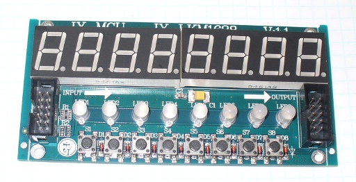
Arduino and TM1638 LED Display Modules

If you need a fast and easy way to add some user input and output to a project, these display modules are interesting and fun.

They contain eight 7-segment red LED digits, eight red/green LEDs and also eight buttons for user input. The units can also be daisy-chained, allowing up to five at once, and a short cable is included with each module, as well as some short spacers and bolts, such as:

TM1638 Numeric Display LED Input Board from PMD Way

The spacers are just long enough to raise the PCB above a surface, however to mount the boards anywhere useful you would need longer ones. You may also want to remove the IDC sockets if you want to mount the module close to the surface of a panel. This would be a simple desoldering task as they are through-hole sockets:

TM1638 Numeric Display LED Input Board from PMD Way

The board is controlled by a TM1638 IC:

TM1638 Numeric Display LED Input Board from PMD Way

This is an LED and interface driver IC from “Titan Micro Electronics“.  You can also buy these ICs from PMD Way. You can also download the datasheet for more details.

Getting Started

Now to make things happen…

Hardware – Connection to an Arduino-compatible board (or other MCU) is quite simple. The pinouts are shown on the rear of the PCB, and match the fitting on the ribbon cable. If you look at the end of the cable as such:

TM1638 Numeric Display LED Input Board from PMD Way

The top-right hole is pin one, with the top-left being pin two, the bottom-right pin nine and bottom-left pin ten. Therefore the pinouts are:

  1. Vcc (5V)
  2. GND
  3. CLK
  4. DIO
  5. STB1
  6. STB2
  7. STB3
  8. STB4
  9. STB5
  10. not connected

For Arduino use, pins 1~4 are the minimum necessary to use one module. Each additional module will require another digital pin connected to STB2, STB3, etc. More on this later. Please note that each module set to full brightness with every LED on consumes 127mA, so it would be wise to use external power with more than one module and other connections with Arduino boards.

Software –  download and install the T1638 library from here. Thanks and kudos to rjbatista at gmail dot com for the library. Initialising modules in the sketch is simple. Include the library with:

#include <TM1638.h>

then use one of the following for each module:

TM1638 module(x, y, z);

x is  the Arduino digital pin connected to the module cable pin 4, y is the Arduino digital pin connected to the module cable pin 3, and z is the strobe pin. So if you had one module with data, clock and strobe connected to pins 8, 7,  and 6 you would use:

TM1638 module(8, 7, 6);

If you had two modules, with module one’s strobe connected to Arduino digital 6, and module two’s strobe connected to digital 5, you would use:

TM1638 module(8, 7, 6);
TM1638 module(8, 7, 5);

and so on for more modules.  Now to control the display…

The bi-colour LEDs

Controlling the red/green LEDs is easy. For reference they are numbered zero to seven from left to right. To turn on or off a single LED, use the following:

module.setLED(TM1638_COLOR_RED, x);  // set LED number x to red
module.setLED(TM1638_COLOR_GREEN, x); // set LED number x to green
module.setLED(TM1638_COLOR_RED+TM1638_COLOR_GREEN, 0); // set LED number x to red and green

Using the method above may be simple it is somewhat inefficient. A better way is to address all of the LEDs in one statement. To do this we send two bytes of data in hexadecimal to the display. The MSB (most significant byte) consists of eight bits, each representing one green LED being on (1) or off (0). The LSB (least significant byte) represents the red LEDs.

An easy way to determine the hexadecimal value to control the LEDs is simple, image you have one row of LEDs – the first eight being green and the second eight being red.  Set each digit to 1 for on and 0 for off. The convert the two binary numbers to hexadecimal and use this function:

module.setLEDs(0xgreenred);

Where green is the hexadecimal number for the green LEDs and red is the hexadecimal number for the red LEDs. For example, to turn on the first three LEDs as red, and the last three as green, the binary representation will be:

00000111 11100000 which in hexadecimal is E007. So we would use:

module.setLEDs(0xE007);

which produces the following:

TM1638 Numeric Display LED Input Board from PMD Way

The 7-segment display

To clear the numeric display (but not the LEDs below), simply use:

module.clearDisplay();

or to turn on every segment AND all the LEDs, use the following

module.setupDisplay(true, 7); // where 7 is intensity (from 0~7)

To display decimal numbers, use the function:

module.setDisplayToDecNumber(a,b,false);

where a is the integer, b is the position for the decimal point (0 for none, 1 for digit 8, 2, for digit 7, 4 for digit 6, 8 for digit 4, etc), and the last parameter (true/false) turns on or off leading zeros. The following sketch demonstrates the use of this function:

#include <TM1638.h>
// define a module on data pin 8, clock pin 9 and strobe pin 7
TM1638 module(8, 9, 7);
unsigned long a=1;
void setup(){}
void loop()
{
 for (a=10000; a<11000; a++)
 {
 module.setDisplayToDecNumber(a,4,false);
 delay(1);
 }
 for (a=10000; a<11000; a++)
 {
 module.setDisplayToDecNumber(a,0,true);
 delay(1);
 }
}

and the results:

One of the most interesting features is the ability to scroll text across one or more displays. To do so doesn’t really need an explanation as the included demonstration sketch:

tm_1638_scrolling_modules_example.pde

included with the TM1638 library is easily followed. Just insert your text in the const char string[], ensure that the module(s) are wired according to the module definition at the start of the sketch and you’re set. To see the available characters, visit the function page. Note that the display is only seven-segments, so some characters may not look perfect, but in context will give you a good idea – for example:

Finally, you can also individually address each segment of each digit. Consider the contents of this array:

byte values[] = { 1, 2, 4, 8, 16, 32, 64, 128 };

each element represents digits 1~8. The value of each element determines which segment of the digit turns on. For segments a~f, dp the values are 1,2,4,6,16,32,64,128. So the results of using the array above in the following function:

module.setDisplay(values);

will be:

TM1638 Numeric Display LED Input Board from PMD Way

Naturally you can combine values for each digit to create your own characters, symbols, etcetera. For example, using the following values:

byte values[] = { 99,99,99,99,99,99,99,99 };

we created:

TM1638 Numeric Display LED Input Board from PMD Way

The buttons

The values of the buttons are returned as a byte value from the function:

module.getButtons();

As there are eight buttons, each one represents one bit of a binary number that is returned as a byte. The button on the left returns decimal one, and the right returns 128. It can also return simultaneous presses, so pressing buttons one and eight returns 129. Consider the following sketch, which returns the values of the button presses in decimal form, then displays the value:

#include <TM1638.h>
// define a module on data pin 8, clock pin 9 and strobe pin 7
TM1638 module(8, 9, 7);
byte buttons;
void setup(){}
void loop()
{
 buttons=module.getButtons();
 module.setDisplayToDecNumber(buttons,0,false);
}

and the results:

A reader from Brazil has used one of the modules as part of a racing simulator – read more about it here, and view his demonstration below.

These display boards are useful and hopefully find a home in your projects.

This post brought to you by pmdway.com – offering everything for makers and electronics enthusiasts, with free delivery worldwide.

To keep up to date with new posts at tronixstuff.com, please subscribe to the mailing list in the box on the right, or follow us on twitter @tronixstuff.