If you need a fast and easy way to add some user input and output to a project, these display modules are interesting and fun.
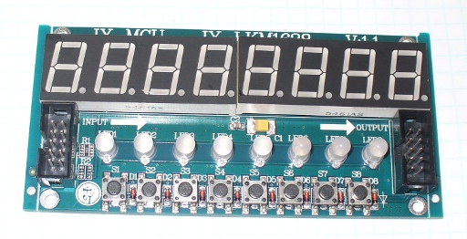
They contain eight 7-segment red LED digits, eight red/green LEDs and also eight buttons for user input. The units can also be daisy-chained, allowing up to five at once, and a short cable is included with each module, as well as some short spacers and bolts, such as:

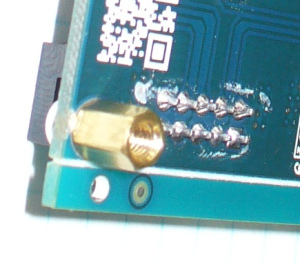
The spacers are just long enough to raise the PCB above a surface, however to mount the boards anywhere useful you would need longer ones. You may also want to remove the IDC sockets if you want to mount the module close to the surface of a panel. This would be a simple desoldering task as they are through-hole sockets:
The board is controlled by a TM1638 IC:

This is an LED and interface driver IC from “Titan Micro Electronics“. You can also buy these ICs from amazon. You can also download the datasheet for more details.
Getting Started
Now to make things happen…
Hardware – Connection to an Arduino-compatible board (or other MCU) is quite simple. The pinouts are shown on the rear of the PCB, and match the fitting on the ribbon cable. If you look at the end of the cable as such:

The top-right hole is pin one, with the top-left being pin two, the bottom-right pin nine and bottom-left pin ten. Therefore the pinouts are:
- Vcc (5V)
- GND
- CLK
- DIO
- STB1
- STB2
- STB3
- STB4
- STB5
- not connected
For Arduino use, pins 1~4 are the minimum necessary to use one module. Each additional module will require another digital pin connected to STB2, STB3, etc. More on this later. Please note that each module set to full brightness with every LED on consumes 127mA, so it would be wise to use external power with more than one module and other connections with Arduino boards.
Software – download and install the T1638 library from here. Thanks and kudos to rjbatista at gmail dot com for the library. Initialising modules in the sketch is simple. Include the library with:
#include <TM1638.h>
then use one of the following for each module:
TM1638 module(x, y, z);
x is the Arduino digital pin connected to the module cable pin 4, y is the Arduino digital pin connected to the module cable pin 3, and z is the strobe pin. So if you had one module with data, clock and strobe connected to pins 8, 7, and 6 you would use:
TM1638 module(8, 7, 6);
If you had two modules, with module one’s strobe connected to Arduino digital 6, and module two’s strobe connected to digital 5, you would use:
TM1638 module(8, 7, 6);
TM1638 module(8, 7, 5);
and so on for more modules. Now to control the display…
The bi-colour LEDs
Controlling the red/green LEDs is easy. For reference they are numbered zero to seven from left to right. To turn on or off a single LED, use the following:
module.setLED(TM1638_COLOR_RED, x);  // set LED number x to red
module.setLED(TM1638_COLOR_GREEN, x); // set LED number x to green
module.setLED(TM1638_COLOR_RED+TM1638_COLOR_GREEN, 0); // set LED number x to red and green
Using the method above may be simple it is somewhat inefficient. A better way is to address all of the LEDs in one statement. To do this we send two bytes of data in hexadecimal to the display. The MSB (most significant byte) consists of eight bits, each representing one green LED being on (1) or off (0). The LSB (least significant byte) represents the red LEDs.
An easy way to determine the hexadecimal value to control the LEDs is simple, image you have one row of LEDs – the first eight being green and the second eight being red. Set each digit to 1 for on and 0 for off. The convert the two binary numbers to hexadecimal and use this function:
module.setLEDs(0xgreenred);
Where green is the hexadecimal number for the green LEDs and red is the hexadecimal number for the red LEDs. For example, to turn on the first three LEDs as red, and the last three as green, the binary representation will be:
00000111 11100000 which in hexadecimal is E007. So we would use:
module.setLEDs(0xE007);
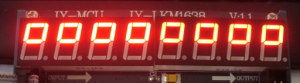
which produces the following:

The 7-segment display
To clear the numeric display (but not the LEDs below), simply use:
module.clearDisplay();
or to turn on every segment AND all the LEDs, use the following
module.setupDisplay(true, 7); // where 7 is intensity (from 0~7)
To display decimal numbers, use the function:
module.setDisplayToDecNumber(a,b,false);
where a is the integer, b is the position for the decimal point (0 for none, 1 for digit 8, 2, for digit 7, 4 for digit 6, 8 for digit 4, etc), and the last parameter (true/false) turns on or off leading zeros. The following sketch demonstrates the use of this function:
#include <TM1638.h>
// define a module on data pin 8, clock pin 9 and strobe pin 7
TM1638 module(8, 9, 7);
unsigned long a=1;
void setup(){}
void loop()
{
 for (a=10000; a<11000; a++)
 {
 module.setDisplayToDecNumber(a,4,false);
 delay(1);
 }
 for (a=10000; a<11000; a++)
 {
 module.setDisplayToDecNumber(a,0,true);
 delay(1);
 }
}
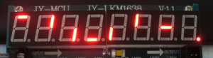
and the results:
One of the most interesting features is the ability to scroll text across one or more displays. To do so doesn’t really need an explanation as the included demonstration sketch:
tm_1638_scrolling_modules_example.pde
included with the TM1638 library is easily followed. Just insert your text in the const char string[], ensure that the module(s) are wired according to the module definition at the start of the sketch and you’re set. To see the available characters, visit the function page. Note that the display is only seven-segments, so some characters may not look perfect, but in context will give you a good idea – for example:
Finally, you can also individually address each segment of each digit. Consider the contents of this array:
byte values[] = { 1, 2, 4, 8, 16, 32, 64, 128 };
each element represents digits 1~8. The value of each element determines which segment of the digit turns on. For segments a~f, dp the values are 1,2,4,6,16,32,64,128. So the results of using the array above in the following function:
module.setDisplay(values);
will be:

Naturally you can combine values for each digit to create your own characters, symbols, etcetera. For example, using the following values:
byte values[] = { 99,99,99,99,99,99,99,99 };
we created:
The buttons
The values of the buttons are returned as a byte value from the function:
module.getButtons();
As there are eight buttons, each one represents one bit of a binary number that is returned as a byte. The button on the left returns decimal one, and the right returns 128. It can also return simultaneous presses, so pressing buttons one and eight returns 129. Consider the following sketch, which returns the values of the button presses in decimal form, then displays the value:
#include <TM1638.h>
// define a module on data pin 8, clock pin 9 and strobe pin 7
TM1638 module(8, 9, 7);
byte buttons;
void setup(){}
void loop()
{
 buttons=module.getButtons();
 module.setDisplayToDecNumber(buttons,0,false);
}
and the results:
A reader from Brazil has used one of the modules as part of a racing simulator – read more about it here, and view his demonstration below.
These display boards are useful and hopefully find a home in your projects.
To keep up to date with new posts at tronixstuff.com, please subscribe to the mailing list in the box on the right, or follow us on x – @tronixstuff.
I hope you enjoyed making this or at least reading about it. If you find this sort of thing interesting, please consider ordering one or more of my books from amazon.
And as always, have fun and make something.


You must be logged in to post a comment.