This is a quick start guide for the Four Digit Seven Segment Display Module and Enclosure from PMD Way. This module offers a neat and bright display which is ideal for numeric or hexadecimal data. It can display the digits 0 to 9 including the decimal point, and the letters A to F. You can also control each segment individually if desired.
Each module contains four 74HC595 shift registers – once of each controls a digit. If you carefully remove the back panel from the enclosure, you can see the pin connections:
If you’re only using one display, use the group of pins at the centre-bottom of the board. From left to right the connections are:
Data out (ignore for single display use)
VCC – connect to a 3.3V or 5V supply
GND – connect to your GND line
SDI – data in – connect to the data out pin on your Arduino/other board
LCK – latch – connect to the output pin on your Arduino or other board that will control the latch
CLK – clock – connect to the output pin on your Arduino or other board that will control the clock signal
For the purposes of our Arduino tutorial, connect VCC to the 5V pin, GND to GND, SDI to D11, LCK to D13 and CLK to D12.
If you are connecting more than one module, use the pins on the left- and right-hand side of the module. Start with the connections from your Arduino (etc) to the right-hand side, as this is where the DIN (data in) pin is located.
Then connect the pins on the left-hand side of the module to the right-hand side of the new module – and so forth. SDO (data out) will connect to the SDI (data in) – with the other pins being identical for connection.
The module schematic is shown below:
Arduino Example Sketch
Once you have made the connections to your Arduino as outlined above, upload the following sketch:
// Demonstration Arduino sketch for four digit, seven segment display with enclosure
// https://pmdway.com/collections/7-segment-numeric-leds/products/four-digit-seven-segment-display-module-and-enclosure
int latchPin = 13;   // connect to LCK pin
intclockPin = 12;   // connect to CLK pin
intdataPin = 11;    // connect to SDI pin

int LED_SEG_TAB[]={
  0xfc,0x60,0xda,0xf2,0x66,0xb6,0xbe,0xe0,0xfe,0xf6,0x01,0xee,0x3e,0x1a,0x7a,0x9e,0x8e,0x01,0x00};
//0     1    2     3    4    5    6    7    8    9   dp   .    a    b    c    d    e    f   off

void setup()
{
  //set pins to output so you can control the shift register
  pinMode(latchPin, OUTPUT);
  pinMode(clockPin, OUTPUT);
  pinMode(dataPin, OUTPUT);
}

void displayNumber(int value, boolean leadingZero)
// break down "value" into digits and store in a,b,c,d
{
  int a,b,c,d;
  a = value / 1000;
  value = value % 1000;
  b = value / 100;
  value = value % 100;
  c = value / 10;
  value = value % 10;
  d = value;

  if (leadingZero==false) // removing leading zeros
  {
    if (a==0 && b>0)                  {
      a = 18;
    }
    if (a==0 && b==0 && c>0)          {
      a = 18;
      b = 18;
    }
    if (a==0 && b==0 && c==0)         {
      a = 18;
      b = 18;
      c = 18;
    }
    if (a==0 && b==0 && c==0 && d==0) {
      a = 18;
      b = 18;
      c = 18;
      d = 18;
    }
  }

  digitalWrite(latchPin, LOW);
  shiftOut(dataPin, clockPin, LSBFIRST, LED_SEG_TAB[d]);
  shiftOut(dataPin, clockPin, LSBFIRST, LED_SEG_TAB[c]);
  shiftOut(dataPin, clockPin, LSBFIRST, LED_SEG_TAB[b]);
  shiftOut(dataPin, clockPin, LSBFIRST, LED_SEG_TAB[a]);
  digitalWrite(latchPin, HIGH);
}

void allOff() // turns off all segments
{
  digitalWrite(latchPin, LOW);
  shiftOut(dataPin, clockPin, LSBFIRST, 0);
  shiftOut(dataPin, clockPin, LSBFIRST, 0);
  shiftOut(dataPin, clockPin, LSBFIRST, 0);
  shiftOut(dataPin, clockPin, LSBFIRST, 0);
  digitalWrite(latchPin, HIGH);
}

void loop()
{
  for (int z=900; z<=1100; z++)
  {
    displayNumber(z, false);
    delay(10);
  }
  delay(1000);
  for (int z=120; z>=0; --z)
  {
    displayNumber(z, true);
    delay(10);
  }
  delay(1000);

  digitalWrite(latchPin, LOW);
  shiftOut(dataPin, clockPin, LSBFIRST, LED_SEG_TAB[14]);
  shiftOut(dataPin, clockPin, LSBFIRST, LED_SEG_TAB[13]);
  shiftOut(dataPin, clockPin, LSBFIRST, LED_SEG_TAB[12]);
  shiftOut(dataPin, clockPin, LSBFIRST, LED_SEG_TAB[11]);
  digitalWrite(latchPin, HIGH);

  delay(1000);

  digitalWrite(latchPin, LOW);
  shiftOut(dataPin, clockPin, LSBFIRST, LED_SEG_TAB[16]);
  shiftOut(dataPin, clockPin, LSBFIRST, LED_SEG_TAB[15]);
  shiftOut(dataPin, clockPin, LSBFIRST, LED_SEG_TAB[14]);
  shiftOut(dataPin, clockPin, LSBFIRST, LED_SEG_TAB[13]);
  digitalWrite(latchPin, HIGH);
  delay(1000);

  digitalWrite(latchPin, LOW);
  shiftOut(dataPin, clockPin, LSBFIRST, LED_SEG_TAB[0]);
  shiftOut(dataPin, clockPin, LSBFIRST, LED_SEG_TAB[1]);
  shiftOut(dataPin, clockPin, LSBFIRST, LED_SEG_TAB[2]);
  shiftOut(dataPin, clockPin, LSBFIRST, LED_SEG_TAB[3]+1);
  digitalWrite(latchPin, HIGH);
  delay(1000);

  digitalWrite(latchPin, LOW);
  shiftOut(dataPin, clockPin, LSBFIRST, LED_SEG_TAB[7]);
  shiftOut(dataPin, clockPin, LSBFIRST, LED_SEG_TAB[6]+1);
  shiftOut(dataPin, clockPin, LSBFIRST, LED_SEG_TAB[5]);
  shiftOut(dataPin, clockPin, LSBFIRST, LED_SEG_TAB[4]);
  digitalWrite(latchPin, HIGH);
  delay(1000);
}
After a moment you should see the display spring into action in the same way as in the demonstration video:
How does it work?
First we define which digital output pins are used for latch, clock and data on lines four to six. On line eight we have created an array which contains values that are sent to the shift registers in the module to display the possible digits and letters. For example, the first – 0xfc – will activate the segments to display a zero, 0x7a for the letter C, and so on.
From line 20 we’ve created a custom function that is used to send a whole number between zero and 9999 to the display. To do so, simply use:
void displayNumber(value, true/false);
where value is the number to display (or variable containing the number) – and the second parameter of true or false. This controls whether you have a leading zero displayed – true for yes, false for no.
For example, to display “0123” you would use:
displayNumber(123, true);
… which results with:
or to display “500” you would use:
displayNumber(500, false);
… which results with:
To turn off all the digits, you need to send zeros to every bit in the shift register, and this is accomplished with the function in the sketch called
allOff();
What about the decimal point?
To turn on the decimal point for a particular digit, add 1 to the value being sent to a particular digit. Using the code from the demonstration sketch to display 87.65 you would use:
In-depth explanation of how the module is controlled
As shown in the schematic above, each digit is controlled by a 74HC595 shift register. Each shift register has eight digital outputs, each of which control an individual segment of each digit. So by sending four bytes of data (one byte = eight bits) you can control each segment of the display.
Each digit’s segments are mapped as follows:
And the outputs from each shift register match the order of segments from left to right. So outputs 0~7 match A~G then decimal point.
For example, to create the number seven with a decimal point, you need to turn on segments A, B, C and DP – which match to the shift register’s outputs 0,1,2,8.
Thus the byte to send to the shift register would be 0b11100001 (or 225 in decimal or 0xE1 in hexadecimal).
Every time you want to change the display you need to re-draw all four (or more if more than one module is connected) digits – so four bytes of data are sent for each display change. The digits are addressed from right to left, so the first byte send is for the last digit – and the last byte is for the first digit.
There are three stages of updating the display.
Set the LCK (latch) line low
Shift out four bytes of data from your microcontroller
Note how the bytes in binary match the map of the digits and their position. For example, the first byte sent was for the fourth digit, and the segment A was turned on. And that’s all there is to it – a neat and simple display.
This post brought to you by pmdway.com – everything for makers and electronics enthusiasts, with free delivery worldwide.
To keep up to date with new posts at tronixstuff.com, please subscribe to the mailing list in the box on the right, or follow us on twitter @tronixstuff.
Sooner or later Arduino enthusiasts and beginners alike will come across the MAX7219 IC. And for good reason, it’s a simple and somewhat inexpensive method of controlling 64 LEDs in either matrix or numeric display form. Furthermore they can be chained together to control two or more units for even more LEDs. Overall – they’re a lot of fun and can also be quite useful, so let’s get started.
Here’s an example of a MAX7219 and another IC which is a functional equivalent, the AS1107 from Austria Microsystems. You might not see the AS1107 around much, but it can be cheaper – so don’t be afraid to use that instead:
At first glance you may think that it takes a lot of real estate, but it saves some as well. As mentioned earlier, the MAX7219 can completely control 64 individual LEDs – including maintaining equal brightness, and allowing you to adjust the brightness of the LEDs either with hardware or software (or both). It can refresh the LEDs at around 800 Hz, so no more flickering, uneven LED displays.
You can even switch the display off for power saving mode, and still send it data while it is off. And another good thing – when powered up, it keeps the LEDs off, so no wacky displays for the first seconds of operation. For more technical information, here is the data sheet: MAX7219.pdf. Now to put it to work for us – we’ll demonstrate using one or more 8 x 8 LED matrix displays, as well as 8 digits of 7-segment LED numbers.
Before continuing, download and install the LedControl Arduino library as it is essential for using the MAX7219.
Controlling LED matrix displays with the MAX7219
First of all, let’s examine the hardware side of things. Here is the pinout diagram for the MAX7219:
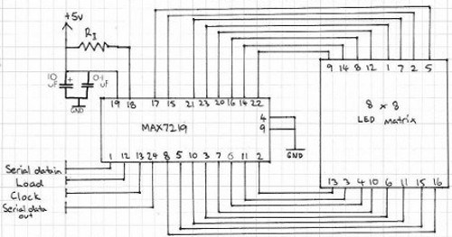
The MAX7219 drives eight LEDs at a time, and by rapidly switching banks of eight your eyes don’t see the changes. Wiring up a matrix is very simple – if you have a common matrix with the following schematic:
connect the MAX7219 pins labelled DP, A~F to the row pins respectively, and the MAX7219 pins labelled DIG0~7 to the column pins respectively. A total example circuit with the above matrix is as follows:
The circuit is quite straight forward, except we have a resistor between 5V and MAX7219 pin 18. The MAX7219 is a constant-current LED driver, and the value of the resistor is used to set the current flow to the LEDs. Have a look at table eleven on page eleven of the data sheet:
You’ll need to know the voltage and forward current for your LED matrix or numeric display, then match the value on the table. E.g. if you have a 2V 20 mA LED, your resistor value will be 28kΩ (the values are in kΩ). Finally, the MAX7219 serial in, load and clock pins will go to Arduino digital pins which are specified in the sketch. We’ll get to that in the moment, but before that let’s return to the matrix modules.
In the last few months there has been a proliferation of inexpensive kits that contain a MAX7219 or equivalent, and an LED matrix. These are great for experimenting with and can save you a lot of work – some examples of which are shown below:
Now for the sketch. You need the following two lines at the beginning of the sketch:
The first pulls in the library, and the second line sets up an instance to control. The four parameters are as follows:
the digital pin connected to pin 1 of the MAX7219 (“data in”)
the digital pin connected to pin 13 of the MAX7219 (“CLK or clock”)
the digital pin connected to pin 12 of the MAX7219 (“LOAD”)
The number of MAX7219s connected.
If you have more than one MAX7219, connect the DOUT (“data out”) pin of the first MAX7219 to pin 1 of the second, and so on. However the CLK and LOAD pins are all connected in parallel and then back to the Arduino.
Next, two more vital functions that you’d normally put in void setup():
lc.shutdown(0,false);
lc.setIntensity(0,8);
The first line above turns the LEDs connected to the MAX7219 on. If you set TRUE, you can send data to the MAX7219 but the LEDs will stay off. The second line adjusts the brightness of the LEDs in sixteen stages. For both of those functions (and all others from the LedControl) the first parameter is the number of the MAX7219 connected. If you have one, the parameter is zero… for two MAX7219s, it’s 1 and so on.
Finally, to turn an individual LED in the matrix on or off, use:
lc.setLed(0,col,row,true);
which turns on an LED positioned at col, row connected to MAX7219 #1. Change TRUE to FALSE to turn it off. These functions are demonstrated in the following sketch:
#include "LedControl.h" //  need the library
LedControl lc=LedControl(12,11,10,1); //

// pin 12 is connected to the MAX7219 pin 1
// pin 11 is connected to the CLK pin 13
// pin 10 is connected to LOAD pin 12
// 1 as we are only using 1 MAX7219

void setup()
{
  // the zero refers to the MAX7219 number, it is zero for 1 chip
  lc.shutdown(0,false);// turn off power saving, enables display
  lc.setIntensity(0,8);// sets brightness (0~15 possible values)
  lc.clearDisplay(0);// clear screen
}
void loop()
{
  for (int row=0; row<8; row++)
  {
    for (int col=0; col<8; col++)
    {
      lc.setLed(0,col,row,true); // turns on LED at col, row
      delay(25);
    }
  }

  for (int row=0; row<8; row++)
  {
    for (int col=0; col<8; col++)
    {
      lc.setLed(0,col,row,false); // turns off LED at col, row
      delay(25);
    }
  }
}
And a quick video of the results:
How about controlling two MAX7219s? Or more? The hardware modifications are easy – connect the serial data out pin from your first MAX7219 to the data in pin on the second (and so on), and the LOAD and CLOCK pins from the first MAX7219 connect to the second (and so on). You will of course still need the 5V, GND, resistor, capacitors etc. for the second and subsequent MAX7219.
You will also need to make a few changes in your sketch. The first is to tell it how many MAX7219s you’re using in the following line:
LedControl lc=LedControl(12,11,10,X);
by replacing X with the quantity. Then whenever you’re using a MAX7219 function, replace the (previously used) zero with the number of the MAX7219 you wish to address. They are numbered from zero upwards, with the MAX7219 directly connected to the Arduino as unit zero, then one etc. To demonstrate this, we replicate the previous example but with two MAX7219s:
#include "LedControl.h" //  need the library
LedControl lc=LedControl(12,11,10,2); //

// pin 12 is connected to the MAX7219 pin 1
// pin 11 is connected to the CLK pin 13
// pin 10 is connected to LOAD pin 12
// 1 as we are only using 1 MAX7219

void setup()
{
  lc.shutdown(0,false);// turn off power saving, enables display
  lc.setIntensity(0,8);// sets brightness (0~15 possible values)
  lc.clearDisplay(0);// clear screen

  lc.shutdown(1,false);// turn off power saving, enables display
  lc.setIntensity(1,8);// sets brightness (0~15 possible values)
  lc.clearDisplay(1);// clear screen
}

void loop()
{
  for (int row=0; row<8; row++)
  {
    for (int col=0; col<8; col++)
    {
      lc.setLed(0,col,row,true); // turns on LED at col, row
      lc.setLed(1,col,row,false); // turns on LED at col, row
      delay(25);
    }
  }

  for (int row=0; row<8; row++)
  {
    for (int col=0; col<8; col++)
    {
      lc.setLed(0,col,row,false); // turns off LED at col, row
      lc.setLed(1,col,row,true); // turns on LED at col, row
      delay(25);
    }
  }
}
And again, a quick demonstration:
Another fun use of the MAX7219 and LED matrices is to display scrolling text. For the case of simplicity we’ll use the LedControl library and the two LED matrix modules from the previous examples.
First our example sketch – it is quite long however most of this is due to defining the characters for each letter of the alphabet and so on. We’ll explain it at the other end!
// based on an orginal sketch by Arduino forum member "danigom"
// http://forum.arduino.cc/index.php?action=profile;u=188950

#include <avr/pgmspace.h>
#include <LedControl.h>

const int numDevices = 2;      // number of MAX7219s used
const long scrollDelay = 75;   // adjust scrolling speed

unsigned long bufferLong [14] = {0};

LedControl lc=LedControl(12,11,10,numDevices);

prog_uchar scrollText[] PROGMEM ={
    "  THE QUICK BROWN FOX JUMPED OVER THE LAZY DOG 1234567890 the quick brown fox jumped over the lazy dog   "};

void setup(){
    for (int x=0; x<numDevices; x++){
        lc.shutdown(x,false);       //The MAX72XX is in power-saving mode on startup
        lc.setIntensity(x,8);       // Set the brightness to default value
        lc.clearDisplay(x);         // and clear the display
    }
}

void loop(){
    scrollMessage(scrollText);
    scrollFont();
}

///////////////////////////////////////////////////////////////////////////////////////////////////////////////////

prog_uchar font5x7 [] PROGMEM = {      //Numeric Font Matrix (Arranged as 7x font data + 1x kerning data)
    B00000000,	//Space (Char 0x20)
    B00000000,
    B00000000,
    B00000000,
    B00000000,
    B00000000,
    B00000000,
    6,

    B10000000,	//!
    B10000000,
    B10000000,
    B10000000,
    B00000000,
    B00000000,
    B10000000,
    2,

    B10100000,	//"
    B10100000,
    B10100000,
    B00000000,
    B00000000,
    B00000000,
    B00000000,
    4,

    B01010000,	//#
    B01010000,
    B11111000,
    B01010000,
    B11111000,
    B01010000,
    B01010000,
    6,

    B00100000,	//$
    B01111000,
    B10100000,
    B01110000,
    B00101000,
    B11110000,
    B00100000,
    6,

    B11000000,	//%
    B11001000,
    B00010000,
    B00100000,
    B01000000,
    B10011000,
    B00011000,
    6,

    B01100000,	//&
    B10010000,
    B10100000,
    B01000000,
    B10101000,
    B10010000,
    B01101000,
    6,

    B11000000,	//'
    B01000000,
    B10000000,
    B00000000,
    B00000000,
    B00000000,
    B00000000,
    3,

    B00100000,	//(
    B01000000,
    B10000000,
    B10000000,
    B10000000,
    B01000000,
    B00100000,
    4,

    B10000000,	//)
    B01000000,
    B00100000,
    B00100000,
    B00100000,
    B01000000,
    B10000000,
    4,

    B00000000,	//*
    B00100000,
    B10101000,
    B01110000,
    B10101000,
    B00100000,
    B00000000,
    6,

    B00000000,	//+
    B00100000,
    B00100000,
    B11111000,
    B00100000,
    B00100000,
    B00000000,
    6,

    B00000000,	//,
    B00000000,
    B00000000,
    B00000000,
    B11000000,
    B01000000,
    B10000000,
    3,

    B00000000,	//-
    B00000000,
    B11111000,
    B00000000,
    B00000000,
    B00000000,
    B00000000,
    6,

    B00000000,	//.
    B00000000,
    B00000000,
    B00000000,
    B00000000,
    B11000000,
    B11000000,
    3,

    B00000000,	///
    B00001000,
    B00010000,
    B00100000,
    B01000000,
    B10000000,
    B00000000,
    6,

    B01110000,	//0
    B10001000,
    B10011000,
    B10101000,
    B11001000,
    B10001000,
    B01110000,
    6,

    B01000000,	//1
    B11000000,
    B01000000,
    B01000000,
    B01000000,
    B01000000,
    B11100000,
    4,

    B01110000,	//2
    B10001000,
    B00001000,
    B00010000,
    B00100000,
    B01000000,
    B11111000,
    6,

    B11111000,	//3
    B00010000,
    B00100000,
    B00010000,
    B00001000,
    B10001000,
    B01110000,
    6,

    B00010000,	//4
    B00110000,
    B01010000,
    B10010000,
    B11111000,
    B00010000,
    B00010000,
    6,

    B11111000,	//5
    B10000000,
    B11110000,
    B00001000,
    B00001000,
    B10001000,
    B01110000,
    6,

    B00110000,	//6
    B01000000,
    B10000000,
    B11110000,
    B10001000,
    B10001000,
    B01110000,
    6,

    B11111000,	//7
    B10001000,
    B00001000,
    B00010000,
    B00100000,
    B00100000,
    B00100000,
    6,

    B01110000,	//8
    B10001000,
    B10001000,
    B01110000,
    B10001000,
    B10001000,
    B01110000,
    6,

    B01110000,	//9
    B10001000,
    B10001000,
    B01111000,
    B00001000,
    B00010000,
    B01100000,
    6,

    B00000000,	//:
    B11000000,
    B11000000,
    B00000000,
    B11000000,
    B11000000,
    B00000000,
    3,

    B00000000,	//;
    B11000000,
    B11000000,
    B00000000,
    B11000000,
    B01000000,
    B10000000,
    3,

    B00010000,	//<
    B00100000,
    B01000000,
    B10000000,
    B01000000,
    B00100000,
    B00010000,
    5,

    B00000000,	//=
    B00000000,
    B11111000,
    B00000000,
    B11111000,
    B00000000,
    B00000000,
    6,

    B10000000,	//>
    B01000000,
    B00100000,
    B00010000,
    B00100000,
    B01000000,
    B10000000,
    5,

    B01110000,	//?
    B10001000,
    B00001000,
    B00010000,
    B00100000,
    B00000000,
    B00100000,
    6,

    B01110000,	//@
    B10001000,
    B00001000,
    B01101000,
    B10101000,
    B10101000,
    B01110000,
    6,

    B01110000,	//A
    B10001000,
    B10001000,
    B10001000,
    B11111000,
    B10001000,
    B10001000,
    6,

    B11110000,	//B
    B10001000,
    B10001000,
    B11110000,
    B10001000,
    B10001000,
    B11110000,
    6,

    B01110000,	//C
    B10001000,
    B10000000,
    B10000000,
    B10000000,
    B10001000,
    B01110000,
    6,

    B11100000,	//D
    B10010000,
    B10001000,
    B10001000,
    B10001000,
    B10010000,
    B11100000,
    6,

    B11111000,	//E
    B10000000,
    B10000000,
    B11110000,
    B10000000,
    B10000000,
    B11111000,
    6,

    B11111000,	//F
    B10000000,
    B10000000,
    B11110000,
    B10000000,
    B10000000,
    B10000000,
    6,

    B01110000,	//G
    B10001000,
    B10000000,
    B10111000,
    B10001000,
    B10001000,
    B01111000,
    6,

    B10001000,	//H
    B10001000,
    B10001000,
    B11111000,
    B10001000,
    B10001000,
    B10001000,
    6,

    B11100000,	//I
    B01000000,
    B01000000,
    B01000000,
    B01000000,
    B01000000,
    B11100000,
    4,

    B00111000,	//J
    B00010000,
    B00010000,
    B00010000,
    B00010000,
    B10010000,
    B01100000,
    6,

    B10001000,	//K
    B10010000,
    B10100000,
    B11000000,
    B10100000,
    B10010000,
    B10001000,
    6,

    B10000000,	//L
    B10000000,
    B10000000,
    B10000000,
    B10000000,
    B10000000,
    B11111000,
    6,

    B10001000,	//M
    B11011000,
    B10101000,
    B10101000,
    B10001000,
    B10001000,
    B10001000,
    6,

    B10001000,	//N
    B10001000,
    B11001000,
    B10101000,
    B10011000,
    B10001000,
    B10001000,
    6,

    B01110000,	//O
    B10001000,
    B10001000,
    B10001000,
    B10001000,
    B10001000,
    B01110000,
    6,

    B11110000,	//P
    B10001000,
    B10001000,
    B11110000,
    B10000000,
    B10000000,
    B10000000,
    6,

    B01110000,	//Q
    B10001000,
    B10001000,
    B10001000,
    B10101000,
    B10010000,
    B01101000,
    6,

    B11110000,	//R
    B10001000,
    B10001000,
    B11110000,
    B10100000,
    B10010000,
    B10001000,
    6,

    B01111000,	//S
    B10000000,
    B10000000,
    B01110000,
    B00001000,
    B00001000,
    B11110000,
    6,

    B11111000,	//T
    B00100000,
    B00100000,
    B00100000,
    B00100000,
    B00100000,
    B00100000,
    6,

    B10001000,	//U
    B10001000,
    B10001000,
    B10001000,
    B10001000,
    B10001000,
    B01110000,
    6,

    B10001000,	//V
    B10001000,
    B10001000,
    B10001000,
    B10001000,
    B01010000,
    B00100000,
    6,

    B10001000,	//W
    B10001000,
    B10001000,
    B10101000,
    B10101000,
    B10101000,
    B01010000,
    6,

    B10001000,	//X
    B10001000,
    B01010000,
    B00100000,
    B01010000,
    B10001000,
    B10001000,
    6,

    B10001000,	//Y
    B10001000,
    B10001000,
    B01010000,
    B00100000,
    B00100000,
    B00100000,
    6,

    B11111000,	//Z
    B00001000,
    B00010000,
    B00100000,
    B01000000,
    B10000000,
    B11111000,
    6,

    B11100000,	//[
    B10000000,
    B10000000,
    B10000000,
    B10000000,
    B10000000,
    B11100000,
    4,

    B00000000,	//(Backward Slash)
    B10000000,
    B01000000,
    B00100000,
    B00010000,
    B00001000,
    B00000000,
    6,

    B11100000,	//]
    B00100000,
    B00100000,
    B00100000,
    B00100000,
    B00100000,
    B11100000,
    4,

    B00100000,	//^
    B01010000,
    B10001000,
    B00000000,
    B00000000,
    B00000000,
    B00000000,
    6,

    B00000000,	//_
    B00000000,
    B00000000,
    B00000000,
    B00000000,
    B00000000,
    B11111000,
    6,

    B10000000,	//`
    B01000000,
    B00100000,
    B00000000,
    B00000000,
    B00000000,
    B00000000,
    4,

    B00000000,	//a
    B00000000,
    B01110000,
    B00001000,
    B01111000,
    B10001000,
    B01111000,
    6,

    B10000000,	//b
    B10000000,
    B10110000,
    B11001000,
    B10001000,
    B10001000,
    B11110000,
    6,

    B00000000,	//c
    B00000000,
    B01110000,
    B10001000,
    B10000000,
    B10001000,
    B01110000,
    6,

    B00001000,	//d
    B00001000,
    B01101000,
    B10011000,
    B10001000,
    B10001000,
    B01111000,
    6,

    B00000000,	//e
    B00000000,
    B01110000,
    B10001000,
    B11111000,
    B10000000,
    B01110000,
    6,

    B00110000,	//f
    B01001000,
    B01000000,
    B11100000,
    B01000000,
    B01000000,
    B01000000,
    6,

    B00000000,	//g
    B01111000,
    B10001000,
    B10001000,
    B01111000,
    B00001000,
    B01110000,
    6,

    B10000000,	//h
    B10000000,
    B10110000,
    B11001000,
    B10001000,
    B10001000,
    B10001000,
    6,

    B01000000,	//i
    B00000000,
    B11000000,
    B01000000,
    B01000000,
    B01000000,
    B11100000,
    4,

    B00010000,	//j
    B00000000,
    B00110000,
    B00010000,
    B00010000,
    B10010000,
    B01100000,
    5,

    B10000000,	//k
    B10000000,
    B10010000,
    B10100000,
    B11000000,
    B10100000,
    B10010000,
    5,

    B11000000,	//l
    B01000000,
    B01000000,
    B01000000,
    B01000000,
    B01000000,
    B11100000,
    4,

    B00000000,	//m
    B00000000,
    B11010000,
    B10101000,
    B10101000,
    B10001000,
    B10001000,
    6,

    B00000000,	//n
    B00000000,
    B10110000,
    B11001000,
    B10001000,
    B10001000,
    B10001000,
    6,

    B00000000,	//o
    B00000000,
    B01110000,
    B10001000,
    B10001000,
    B10001000,
    B01110000,
    6,

    B00000000,	//p
    B00000000,
    B11110000,
    B10001000,
    B11110000,
    B10000000,
    B10000000,
    6,

    B00000000,	//q
    B00000000,
    B01101000,
    B10011000,
    B01111000,
    B00001000,
    B00001000,
    6,

    B00000000,	//r
    B00000000,
    B10110000,
    B11001000,
    B10000000,
    B10000000,
    B10000000,
    6,

    B00000000,	//s
    B00000000,
    B01110000,
    B10000000,
    B01110000,
    B00001000,
    B11110000,
    6,

    B01000000,	//t
    B01000000,
    B11100000,
    B01000000,
    B01000000,
    B01001000,
    B00110000,
    6,

    B00000000,	//u
    B00000000,
    B10001000,
    B10001000,
    B10001000,
    B10011000,
    B01101000,
    6,

    B00000000,	//v
    B00000000,
    B10001000,
    B10001000,
    B10001000,
    B01010000,
    B00100000,
    6,

    B00000000,	//w
    B00000000,
    B10001000,
    B10101000,
    B10101000,
    B10101000,
    B01010000,
    6,

    B00000000,	//x
    B00000000,
    B10001000,
    B01010000,
    B00100000,
    B01010000,
    B10001000,
    6,

    B00000000,	//y
    B00000000,
    B10001000,
    B10001000,
    B01111000,
    B00001000,
    B01110000,
    6,

    B00000000,	//z
    B00000000,
    B11111000,
    B00010000,
    B00100000,
    B01000000,
    B11111000,
    6,

    B00100000,	//{
    B01000000,
    B01000000,
    B10000000,
    B01000000,
    B01000000,
    B00100000,
    4,

    B10000000,	//|
    B10000000,
    B10000000,
    B10000000,
    B10000000,
    B10000000,
    B10000000,
    2,

    B10000000,	//}
    B01000000,
    B01000000,
    B00100000,
    B01000000,
    B01000000,
    B10000000,
    4,

    B00000000,	//~
    B00000000,
    B00000000,
    B01101000,
    B10010000,
    B00000000,
    B00000000,
    6,

    B01100000,	// (Char 0x7F)
    B10010000,
    B10010000,
    B01100000,
    B00000000,
    B00000000,
    B00000000,
    5
};

void scrollFont() {
    for (int counter=0x20;counter<0x80;counter++){
        loadBufferLong(counter);
        delay(500);
    }
}

// Scroll Message
void scrollMessage(prog_uchar * messageString) {
    int counter = 0;
    int myChar=0;
    do {
        // read back a char
        myChar =  pgm_read_byte_near(messageString + counter);
        if (myChar != 0){
            loadBufferLong(myChar);
        }
        counter++;
    }
    while (myChar != 0);
}
// Load character into scroll buffer
void loadBufferLong(int ascii){
    if (ascii >= 0x20 && ascii <=0x7f){
        for (int a=0;a<7;a++){                      // Loop 7 times for a 5x7 font
            unsigned long c = pgm_read_byte_near(font5x7 + ((ascii - 0x20) * 8) + a);     // Index into character table to get row data
            unsigned long x = bufferLong [a*2];     // Load current scroll buffer
            x = x | c;                              // OR the new character onto end of current
            bufferLong [a*2] = x;                   // Store in buffer
        }
        byte count = pgm_read_byte_near(font5x7 +((ascii - 0x20) * 8) + 7);     // Index into character table for kerning data
        for (byte x=0; x<count;x++){
            rotateBufferLong();
            printBufferLong();
            delay(scrollDelay);
        }
    }
}
// Rotate the buffer
void rotateBufferLong(){
    for (int a=0;a<7;a++){                      // Loop 7 times for a 5x7 font
        unsigned long x = bufferLong [a*2];     // Get low buffer entry
        byte b = bitRead(x,31);                 // Copy high order bit that gets lost in rotation
        x = x<<1;                               // Rotate left one bit
        bufferLong [a*2] = x;                   // Store new low buffer
        x = bufferLong [a*2+1];                 // Get high buffer entry
        x = x<<1;                               // Rotate left one bit
        bitWrite(x,0,b);                        // Store saved bit
        bufferLong [a*2+1] = x;                 // Store new high buffer
    }
}
// Display Buffer on LED matrix
void printBufferLong(){
  for (int a=0;a<7;a++){                    // Loop 7 times for a 5x7 font
    unsigned long x = bufferLong [a*2+1];   // Get high buffer entry
    byte y = x;                             // Mask off first character
    lc.setRow(3,a,y);                       // Send row to relevent MAX7219 chip
    x = bufferLong [a*2];                   // Get low buffer entry
    y = (x>>24);                            // Mask off second character
    lc.setRow(2,a,y);                       // Send row to relevent MAX7219 chip
    y = (x>>16);                            // Mask off third character
    lc.setRow(1,a,y);                       // Send row to relevent MAX7219 chip
    y = (x>>8);                             // Mask off forth character
    lc.setRow(0,a,y);                       // Send row to relevent MAX7219 chip
  }
}
The pertinent parts are at the top of the sketch – the following line sets the number of MAX7219s in the hardware:
const int numDevices = 2;
The following can be adjusted to change the speed of text scrolling:
const long scrollDelay = 75;
… then place the text to scroll in the following (for example):
prog_uchar scrollText[] PROGMEM ={
    "  THE QUICK BROWN FOX JUMPED OVER THE LAZY DOG 1234567890 the quick brown fox jumped over the lazy dog   "};
Finally – to scroll the text on demand, use the following:
scrollMessage(scrollText);
You can then incorporate the code into your own sketches. And a video of the example sketch in action:
Although we used the LedControl library, there are many others out there for scrolling text. One interesting example is Parola – which is incredibly customisable.
Controlling LED numeric displays with the MAX7219
Using the MAX7219 and the LedControl library you can also drive numeric LED displays – up to eight digits from the one MAX7219. This gives you the ability to make various numeric displays that are clear to read and easy to control. When shopping around for numeric LED displays, make sure you have the common-cathode type.
Connecting numeric displays is quite simple, consider the following schematic which should appear familiar by now:
The schematic shows the connections for modules or groups of up to eight digits. Each digit’s A~F and dp (decimal point) anodes connect together to the MAX7219, and each digit’s cathode connects in order as well. The MAX7219 will display each digit in turn by using one cathode at a time. Of course if you want more than eight digits, connect another MAX7219 just as we did with the LED matrices previously.
The required code in the sketch is identical to the LED matrix code, however to display individual digits we use:
lc.setDigit(A, B, C, D);
where A is the MAX7219 we’re using, B is the digit to use (from a possible 0 to 7), C is the digit to display (0~9… if you use 10~15 it will display A~F respectively) and D is false/true (digit on or off). You can also send basic characters such as a dash “-” with the following:
lc.setChar(A, B,'-',false);
Now let’s put together an example of eight digits:
#include "LedControl.h" //  need the library
LedControl lc=LedControl(12,11,10,1); // lc is our object
// pin 12 is connected to the MAX7219 pin 1
// pin 11 is connected to the CLK pin 13
// pin 10 is connected to LOAD pin 12
// 1 as we are only using 1 MAX7219
void setup()
{
  // the zero refers to the MAX7219 number, it is zero for 1 chip
  lc.shutdown(0,false);// turn off power saving, enables display
  lc.setIntensity(0,8);// sets brightness (0~15 possible values)
  lc.clearDisplay(0);// clear screen
}
void loop()
{
  for (int a=0; a<8; a++)
  {
    lc.setDigit(0,a,a,true);
    delay(100);
  }
  for (int a=0; a<8; a++)
  {
    lc.setDigit(0,a,8,1);
    delay(100);
  }
  for (int a=0; a<8; a++)
  {
    lc.setDigit(0,a,0,false);
    delay(100);
  }
  for (int a=0; a<8; a++)
  {
    lc.setChar(0,a,' ',false);
    delay(100);
  }
  for (int a=0; a<8; a++)
  {
    lc.setChar(0,a,'-',false);
    delay(100);
  }
  for (int a=0; a<8; a++)
  {
    lc.setChar(0,a,' ',false);
    delay(100);
  }
}
and the sketch in action:
Conclusion
We have only scratched the surface of what is possible with the MAX7219 and compatible parts. They’re loads of fun and quite useful as well.
This post brought to you by pmdway.com – everything for makers and electronics enthusiasts, with free delivery worldwide.
To keep up to date with new posts at tronixstuff.com, please subscribe to the mailing list in the box on the right, or follow us on twitter @tronixstuff.
As an increasing number of people enjoy experimenting with retro-hardware and electronics – especially stuff with numerical LED displays – they have discovered the classic MC14489 LED display driver.
The MC14489 (originally from Motorola) can drive five seven-segment LED numbers with decimal point, or a combination of numbers and separate LEDs. You can also daisy-chain more than one to drive more digits, and it’s controlled with a simple serial data-clock method in the same way as a 74HC595 shift register.
For the purpose of the tutorial we’ll show you how to send commands easily from your Arduino or compatible board to control a five-digit 7-segment LED display module – and the instructions are quite simple so they should translate easily to other platforms. Once you have mastered the single module, using more than one MC14489 will be just as easy. So let’s get started.
Hardware
Before moving forward, download the data sheet (pdf). You will need to refer to this as you build the circuit(s). And here’s our subject in real life:
For our demonstration display we’ll be using a vintage HP 5082-7415 LED display module. However you can use almost any 7-segment modules as long as they’re common-cathode. If you’re using a four-digit module and want an extra digit, you can add another single digit display.
Connecting the MC14489 to an LED display isn’t complex at all. From the data sheet consider Figure 9:
Each of the anode control pins from the MC14489 connect to the matching anodes on your display module, and the BANK1~5 pins connect to the matching digit cathode pins on the display module. You can find the MC14489 pin assignments on page 1 of the data sheet. Seeing as this is chapter fifty-one – by now you should be confident with finding such information on the data sheets, so I will be encouraging you to do a little more of the work.
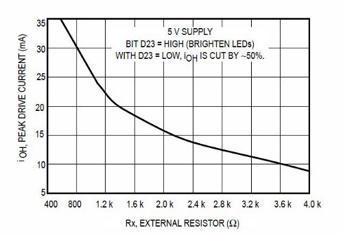
Interesting point – you don’t need current-limiting resistors. However you do need the resistor Rx – this controls the current flow to each LED segment. But which value to use? You need to find out the forward current of your LED display (for example 20 mA) then check Figure 7 on page 7 of the data sheet:
To be conservative I’m using a value of 2k0 for Rx, however you can choose your own based on the data sheet for your display and the graph above. Next – connect the data, clock and enable pins of the MC14489 to three Arduino digital pints – for our example we’re using 5, 6 and 7 for data, clock and enable respectively.
Then it’s just 5V and GND to Arduino 5V and GND – and put a 0.1uF capacitor between 5V and GND. Before moving on double-check the connections – especially between the MC14489 and the LED display.
Controlling the MC14489
To control the display we need to send data to two registers in the MC14489 – the configuration register (one byte) and the display register (three bytes). See page 9 of the data sheet for the overview.
The MC14489 will understand that if we send out one byte of data it is to send it the configuration register, and if it receives three bytes of data to send it to the display register. To keep things simple we’ll only worry about the first bit (C0) in the configuration register – this turns the display outputs on or off. To do this, use the following:
digitalWrite(enable, LOW);
shiftOut(data, clock, MSBFIRST, B00000001); // used binary for clarity, however you can use decimal or hexadecimal numbers
digitalWrite(enable, HIGH);
delay(10);
and to turn it off, send bit C0 as zero. The small delay is necessary after each command.
Once you have turned the display on – the next step is to send three bytes of data which represent the numbers to display and decimal points if necessary. Review the table on page 8 of the data sheet. See how they have the binary nibble values for the digits in the third column.
Thankfully the nibble for each digit is the binary value for that digit. Furthermore you might want to set the decimal point – that is set using three bits in the first nibble of the three bytes (go back to page 9 and see the display register). Finally you can halve the brightness by setting the very first bit to zero (or one for full brightness).
As an example for that – if you want to display 5.4321 the three bytes of data to send in binary will be:
1101 0101 0100 0011 0010 0001
Let’s break that down. The first bit is 1 for full brightness, then the next three bits (101) turn on the decimal point for BANK5 (the left-most digit). Then you have five nibbles of data, one for each of the digits from left to right. So there’s binary for 5, then four, then three, then two, then one.
To demonstrate everything described so far, it’s been neatly packaged into our first example sketch:
// Example 51.1
// Motorola MC14489 with HP 5082-7415 5-digit, 7-segment LED display
// 2k0 resistor on MC14489 Rx pin
// John Boxall 2013 CC by-sa-nc
// define pins for data from Arduino to MC14489
// we treat it just like a 74HC595
int data = 5;
int clock = 6;
int enable = 7;
void setup()
{
 pinMode(data, OUTPUT);
 pinMode(enable, OUTPUT);
 pinMode(clock, OUTPUT);
 displayOn(); // display defaults to off at power-up
}
void displayTest1()
// displays 5.4321
{
 digitalWrite(enable, LOW); // send 3 bytes to display register. See data sheet page 9
 // you can also insert decimal or hexadecimal numbers in place of the binary numbers
 // we're using binary as you can easily match the nibbles (4-bits) against the table
 // in data sheet page 8
 shiftOut(data, clock, MSBFIRST, B11010101); // D23~D16
 shiftOut(data, clock, MSBFIRST, B01000011); // D15~D8
 shiftOut(data, clock, MSBFIRST, B00100001); // D7~D0
 digitalWrite(enable, HIGH);
 delay(10);
}
void displayTest2()
// displays ABCDE
{
 digitalWrite(enable, LOW); // send 3 bytes to display register. See data sheet page 9
 // you can also insert decimal or hexadecimal numbers in place of the binary numbers
 // we're using binary as you can easily match the nibbles (4-bits) against the table
 // in data sheet page 8
 shiftOut(data, clock, MSBFIRST, B10001010); // D23~D16
 shiftOut(data, clock, MSBFIRST, B10111100); // D15~D8
 shiftOut(data, clock, MSBFIRST, B11011110); // D7~D0
 digitalWrite(enable, HIGH);
 delay(10);
}
void displayOn()
// turns on display
{
 digitalWrite(enable, LOW);
 shiftOut(data, clock, MSBFIRST, B00000001);
 digitalWrite(enable, HIGH);
 delay(10);
}
void displayOff()
// turns off display
{
 digitalWrite(enable, LOW);
 shiftOut(data, clock, MSBFIRST, B00000000);
 digitalWrite(enable, HIGH);
 delay(10);
}
void loop()
{
 displayOn();
 displayTest1();
 delay(1000);
 displayTest2();
 delay(1000);
 displayOff();
 delay(500);
}
… with the results in the following video:
Now that we can display numbers and a few letters with binary, life would be easier if there was a way to take a number and just send it to the display.
So consider the following function that takes an integer between 0 and 99999, does the work and sends it to the display:
void displayIntLong(long x)
// takes a long between 0~99999 and sends it to the MC14489
{
 int numbers[5];
 byte a=0;
 byte b=0;
 byte c=0; // will hold the three bytes to send to the MC14489

 // first split the incoming long into five separate digits
 numbers[0] = int ( x / 10000 ); // left-most digit (will be BANK5)
 x = x % 10000;
 numbers[1] = int ( x / 1000 );
 x = x % 1000;
 numbers[2] = int ( x / 100 );
 x = x % 100;
 numbers[3] = int ( x / 10 );
 x = x % 10;
 numbers[4] = x % 10; // right-most digit (will be BANK1)

 // now to create the three bytes to send to the MC14489
 // build byte c which holds digits 4 and 5
 c = numbers[3];
 c = c << 4; // move the nibble to the left
 c = c | numbers[4];
 // build byte b which holds digits 3 and 4
 b = numbers [1];
 b = b << 4;
 b = b | numbers[2];
 // build byte a which holds the brightness bit, decimal points and digit 1
 a = B10000000 | numbers[0]; // full brightness, no decimal points

 // now send the bytes to the MC14489
 digitalWrite(enable, LOW);
 shiftOut(data, clock, MSBFIRST, a);
 shiftOut(data, clock, MSBFIRST, b);
 shiftOut(data, clock, MSBFIRST, c);
 digitalWrite(enable, HIGH);
 delay(10);
}
So how does that work? First it splits the 5-digit number into separate digits and stores them in the array numbers[]. It then places the fourth digit into a byte, then moves the data four bits to the left – then we bitwise OR the fifth digit into the same byte. This leaves us with a byte of data containing the nibbles for the fourth and fifth digit.
The process is repeated for digits 2 and 3. Finally the brightness bit and decimal point bits are assigned to another byte which then has the first digit’s nibble OR’d into it. Which leaves us with bytes a, b and c ready to send to the MC14489.
Note that there isn’t any error-checking – however you could add a test to check that the number to be displayed was within the parameter, and if not either switch off the display (see example 51.1) or throw up all the decimal points or … whatever you want.
Here’s our final demonstration sketch (example 51.2)
// Example 51.2
// Motorola MC14489 with HP 5082-7415 5-digit, 7-segment LED display
// 2k0 resistor on MC14489 Rx pin
// John Boxall 2013 CC by-sa-nc

// define pins for data from Arduino to MC14489
// we treat it just like a 74HC595
int data = 5;
int clock = 6;
int enable = 7;
long i;
void setup()
{
randomSeed(analogRead(0));
pinMode(data, OUTPUT);
pinMode(enable, OUTPUT);
pinMode(clock, OUTPUT);
displayOn(); // display defaults to off at power-up
}

void displayOn()
// turns on display
{
digitalWrite(enable, LOW);
shiftOut(data, clock, MSBFIRST, B00000001);
digitalWrite(enable, HIGH);
delay(10);
}

void displayOff()
// turns off display
{
digitalWrite(enable, LOW);
shiftOut(data, clock, MSBFIRST, B00000000);
digitalWrite(enable, HIGH);
delay(10);
}

void displayIntLong(long x)
// takes a long between 0~99999 and sends it to the MC14489
{
int numbers[5];
byte a=0;
byte b=0;
byte c=0; // will hold the three bytes to send to the MC14489

// first split the incoming long into five seperate digits
numbers[0] = int ( x / 10000 ); // left-most digit (will be BANK5)
x = x % 10000;
numbers[1] = int ( x / 1000 );
x = x % 1000;
numbers[2] = int ( x / 100 );
x = x % 100;
numbers[3] = int ( x / 10 );
x = x % 10;
numbers[4] = x % 10; // right-most digit (will be BANK1)

// now to create the three bytes to send to the MC14489
// build byte a which holds the brightness bit, decimal points and digit 1
a = B10000000 | numbers[0]; // full brightness, no decimal points
// build byte b which holds digits 3 and 4
b = numbers [1];
b = b << 4;
b = b | numbers[2];
// build byte c which holds digits 4 and 5
c = numbers[3];
c = c << 4; // move the nibble to the left
c = c | numbers[4];

// now send the bytes to the MC14489
digitalWrite(enable, LOW);
shiftOut(data, clock, MSBFIRST, a);
shiftOut(data, clock, MSBFIRST, b);
shiftOut(data, clock, MSBFIRST, c);
digitalWrite(enable, HIGH);
delay(10);
}

void loop()
{
i = random(0,100000);
displayIntLong(i);
delay(200);
}
…which results in the following video:
You can also display the letters A to F by sending the values 10 to 15 respectivel to each digit’s nibble. However that would be part of a larger application, which you can (hopefully) by now work out for yourself. Furthermore there’s some other characters that can be displayed – however trying to display the alphabet using 7-segment displays is somewhat passé. Instead, get some 16-segment LED modules or an LCD.
Finally, you can cascade more than one MC14489 to control more digits. Just run a connection from the data out pin on the first MC14889 to the data pin of the second one, and all the clock and enable lines together. Then send out more data – see page 11 of the data sheet. If you’re going to do that in volume other ICs may be a cheaper option and thus lead you back to the MAX7219.
Conclusion
For a chance find the MC14489 is a fun an inexpensive way to drive those LED digit displays. We haven’t covered every single possible option or feature of the part – however you will now have the core knowledge to go further with the MC14489 if you need to move further with it.
This post brought to you by pmdway.com – everything for makers and electronics enthusiasts, with free delivery worldwide.
To keep up to date with new posts at tronixstuff.com, please subscribe to the mailing list in the box on the right, or follow us on twitter @tronixstuff.
In this article we examine a five digit, seven-segment LED display from Hewlett-Packard, the 5082-7415:
We realise they’re most likely now pure unobtanium, but we like some old display p0rn so here you go.
According to the data sheet (HP 5082-series.pdf) and other research this was available for a period of time around 1976 and used with other 5082-series modules in other HP products. Such as the Hewlett-Packard 3x series of calculators, for example:
Using the display is very easy – kudos to the engineers at HP for making a simple design that could be reusable in many applications. The 5082-7415 is a common-cathode unit and wiring is very simple – there are the usual eight anodes for segments a~f and the decimal point, and the five cathodes.
As this module isn’t too easily replaceable, I was very conservative with the power supply – feeding just under 1.6V at 10mA to each of the anode pins. A quick test proved very promising:
Excellent – it worked! But now to get it displaying some sort of interesting way. Using the following hardware…
Don’t forget to use the data sheet (HP 5082-series.pdf). You don’t have to use Arduino – any microcontroller with the appropriate I/O can take care of this.
Here is a simple Arduino sketch that scrolls through the digits with and then without the decimal point:
// Arduino sketch to demonstrate HP 5082-7415 LED Display unit
// John Boxall, April 2012
int clockPin=6;
int latchPin=7;
int dataPin=8;
// array for cathodes - sent to second shift register
byte digits[]={
  B10000000,
  B01000000,
  B00100000,
  B00010000,
  B00001000,
  B11111000}; // use digits[6] to turn all on
// array for anodes (to display 0~0) - sent to first shift register
byte numbers[]={
  B11111100,
  B01100000,
  B11011010,
  B11110010,
  B01100110,
  B10110110,
  B10111110,
  B11100000,
  B11111110,
  B11110110};
void setup()
{
  pinMode(clockPin, OUTPUT);
  pinMode(latchPin, OUTPUT);
  pinMode(dataPin, OUTPUT);
}
void loop()
{
  int i;
  for ( i=0 ; i<10; i++ )
  {
    digitalWrite(latchPin, LOW);
    shiftOut(dataPin, clockPin, LSBFIRST, digits[6]);
    shiftOut(dataPin, clockPin, LSBFIRST, numbers[i]);
    digitalWrite(latchPin, HIGH);
    delay(250);
  }
  // now repeat with decimal point
  for ( i=0 ; i<10; i++ )
  {
    digitalWrite(latchPin, LOW);
    shiftOut(dataPin, clockPin, LSBFIRST, digits[6]);
    shiftOut(dataPin, clockPin, LSBFIRST, numbers[i]+1);
    digitalWrite(latchPin, HIGH);
    delay(250);
  }
}
And the results:
Now for something more useful. Here is a function that sends a single digit to a position on the display with the option of turning the decimal point on or off:
void displayDigit(int value, int posit, boolean decPoint)
// displays integer value at digit position posit with decimal point on/off
{
 digitalWrite(latchPin, LOW);
 shiftOut(dataPin, clockPin, LSBFIRST, digits[posit]);
 if (decPoint==true)
 {
 shiftOut(dataPin, clockPin, LSBFIRST, numbers[value]+1);
 }
 else
 {
 shiftOut(dataPin, clockPin, LSBFIRST, numbers[value]);
 }
 digitalWrite(latchPin, HIGH);
}
So if you wanted to display the number three in the fourth digit, with the decimal point – use
displayDigit(3,3,true);
with the following result:
We make use of the displayDigit() function in our next sketch. We introduce a new function:
displayInteger(number,cycles);
It accepts a long integer between zero and 99999 (number) and displays it on the module for cycles times:
// Arduino sketch to demonstrate HP 5082-7415 LED Display unit
// Displays numbers on request
// John Boxall, April 2012
int clockPin=6;
int latchPin=7;
int dataPin=8;
// array for cathodes - sent to second shift register
byte digits[]={
 B10000000,
 B01000000,
 B00100000,
 B00010000,
 B00001000,
 B11111000}; // use digits[6] to turn all on
// array for anodes (to display 0~0) - sent to first shift register
byte numbers[]={
 B11111100,
 B01100000,
 B11011010,
 B11110010,
 B01100110,
 B10110110,
 B10111110,
 B11100000,
 B11111110,
 B11110110};
void setup()
{
 pinMode(clockPin, OUTPUT);
 pinMode(latchPin, OUTPUT);
 pinMode(dataPin, OUTPUT);
 randomSeed(analogRead(0));
}
void clearDisplay()
// turns off all digits
{
 digitalWrite(latchPin, LOW);
 shiftOut(dataPin, clockPin, LSBFIRST, 0);
 shiftOut(dataPin, clockPin, LSBFIRST, 0);
 digitalWrite(latchPin, HIGH);
}
void displayDigit(int value, int posit, boolean decPoint)
// displays integer value at digit position posit with decimal point on/off
{
 digitalWrite(latchPin, LOW);
 shiftOut(dataPin, clockPin, LSBFIRST, digits[posit]);
 if (decPoint==true)
 {
 shiftOut(dataPin, clockPin, LSBFIRST, numbers[value]+1);
 }
 else
 {
 shiftOut(dataPin, clockPin, LSBFIRST, numbers[value]);
 }
 digitalWrite(latchPin, HIGH);
}
void displayInteger(long number,int cycles)
// displays a number 'number' on the HP display.
{
 long i,j,k,l,z;
 float f;
 clearDisplay();
 for (z=0; z
void loop()
{
 long l2;
 l2=random(0,100001);
 displayInteger(l2,400);
}
For demonstration purposes the sketch displays random numbers, as shown in the video below:
Update – four-digit versions…
They worked very nicely and can be driven in the same method as the 5082-7415s descibed earlier. In the following video we have run the same sketches with the new displays:
This post brought to you by pmdway.com – offering everything for makers and electronics enthusiasts, with free delivery worldwide.
To keep up to date with new posts at tronixstuff.com, please subscribe to the mailing list in the box on the right, or follow us on twitter @tronixstuff.


 David J Hicks, http://www.hpmuseum.org/")


You must be logged in to post a comment.