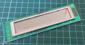
After looking for some displays to use with another (!) clock, I came across some 12-digit numeric LCD displays. They aren’t anything flash, and don’t have a back light – however they were very cheap. The purpose of this tutorial is to show you how they are used with an Arduino in the simplest manner possible.
Update 2025 – These displays are most likely off the market, however there were some on eBay when I looked. However we’ll keep this post up for reference. I don’t have any displays anymore.
Moving forward – the modules look like OEM modules for desktop office phones from the 1990s:
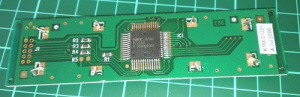
With a quick search on the Internet you will find a few sellers offering them for a dollar each. The modules (data sheet) use the NEC PD7225 controller IC (data sheet):
They aren’t difficult to use, so we’ll run through set up and operation with a few examples.
Hardware setup
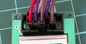
First you’ll need to solder some sort of connection to the module – such as 2×5 header pins. This makes it easy to wire it up to a breadboard or a ribbon cable:
The rest of the circuitry is straight-forward. There are ten pins in two rows of five, and with the display horizontal and the pins on the right, they are numbered as such:
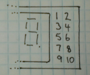
Now make the following connections:
- LCD pin 1 to 5V
- LCD pin 2 to GND
- LCD pin 3 to Arduino D4
- LCD pin 4 to Arduino D5
- LCD pin 5 to Arduino D6
- LCD pin 6 to Arduino D7
- LCD pin 7 – not connected
- LCD pin 8 – Arduino D8
- LCD pin 9 to the centre pin of a 10k trimpot – whose other legs connect to 5V and GND. This is used to adjust the contrast of the LCD.
The Arduino digital pins that are used can be changed – they are defined in the header file (see further on). If you were curious as to how low-current these modules are:
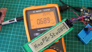
That’s 0.689 mA- not bad at all. Great for battery-powered operations. Now that you’ve got the module wired up, let’s get going with some demonstration sketches.
Software setup
The sketches used in this tutorial are based on work by Jeff Albertson and Robert Mech, so kudos to them – however we’ve simplified them a little to make use easier. We’ll just cover the functions required to display data on the LCD. However feel free to review the sketches and files along with the controller chip datasheet as you’ll get an idea of how the controller is driven by the Arduino.
When using the LCD module you’ll need the following header file in the same folder as your sketch.
/* Header file for Arduino and KTM-S1201 LCD module
Originally Written by Jeff Albertson Ver 1.0
Modifications and code normalisation by Robert W. Mech rob@mechsoftware.com
Modified by John Boxall 11/March/2013

These are the pins that are output on the KTM-S1201

LCD pin number
Pin 1 LcdVcc +5V dc power
pin 2 LcdVss GND
pin 3 LcdnSck Not Serial clock
pin 4 LcdSi Serial data
pin 5 LcdCnD Select Command or Data mode
pin 6 LcdnRes Reset LCD
pin 7 LcdnBus LCD not busy
pin 8 LcdnCs LCD not Chip select
pin 9 Pot wiper Vlc LCD Contrast Connect POT between pin 9 and GND
pin 10 NC
*/

// Here we set which LCD pins will connect to which Arduino pin
#define LcdSck 4 //Not Serial clock
#define LcdSi 5 //Serial data in
#define LcdCnD 6 //Command or Not data in
#define LcdnRes 7 //Not reset low = reset
#define LcdnBus 9// Not Busy output from LCD not used if delay(1) after LcdnCs changes
#define LcdnCs 8 //Not Chip select Low = LCD selected


// Put a delay(1) after every LcdnCs change or check LcdnBus
#define t 100
#define t1 10

// The Not Chip select pin is the only unique
// Pin on the LCD all other pins can be paralleled
// for more ktm-s1201 displays
#define _Mode 0x40
#define _USync 0x31
#define _FBlink 0x1b
#define _SBlink 0x1a
#define _NoBlink 0x18
#define _DispOn 0x11
#define _Decode 0x15
#define _NoDecode 0x14
#define _LoadPtr 0xE0
#define _SetDp 0xb8 // Set decimal point (Dp)
#define _ClearDp 0x9f // Clear decimal point (Dp)
#define _ClearDsp 0x20 // Clear display memory

// To set Dp you must be in NoDecode mode and point to character (LoadPtr)
// --- 0x01
//0x10 | | 0x02
//0x20 ---
//0x40 | | 0x04
//0x80 --- o 0x08

#define _cet 0x31 // Celsius
#define _ 0x0 // Space
#define _A 0x77 //
#define _B 0xF4 //
#define _C 0xE0 //
#define _D 0xE6 //
#define _E 0xF1 //
#define _F 0x71 //
#define _G 0xD5 //
#define _H 0x74 //
#define _I 0x04 //
#define _J 0x86 //
#define _K 0x70 //
#define _L 0xD0 //
#define _M 0x76 //
#define _N 0x64 //
#define _O 0xE4 //
#define _P 0x73 //
#define _Q 0xDF //
#define _R 0x60 //
#define _S 0xB5 //
#define _T 0xF0 //
#define _U 0xC4 //
#define _V 0xD6 //
#define _W 0xF6 //
#define _X 0x56 //
#define _Y 0x72 //
#define _Z 0xEB //
#define _1 0x06 //
#define _2 0xE3 //
#define _3 0xA7 //
#define _4 0x36 //
#define _5 0xB5 //
#define _6 0xF4 //
#define _7 0x07 //
#define _8 0xF7 //
#define _9 0x37 //
#define _0 0xD7 //
#define _DASH 0x20 //
#define _DEGREE 0x33 //
Then every time you open a sketch that uses the header file, it should appear in a tab next to the main sketch, for example:
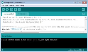
There’s also a group of functions and lines required in your sketch. We’ll run through those now – so download the first example sketch, add the header file and upload it. Your results should be the same as the video below:
So how did that work? Take a look at the sketch you uploaded. You need all the functions between the two lines of “////////////////////////” and also the five lines in void setup(). Then you can display a string of text or numbers using
ktmWriteString();
which was used in void loop(). You can use the digits 0~9, the alphabet (well, what you can do with 7-segments), the degrees symbol (use an asterix – “*”) and a dash (use – “-“). So if your sketch can put together the data to display in a string, then that’s taken care of.
If you want to clear the screen, use:
ktmCommand(_ClearDsp);
Next – to individually place digits on the screen, use the function:
tmPrnNumb(n,p,d,l);
Where n is the number to be displayed (zero or a positive integer), p is the position on the LCD for the number’s (the positions from left to right are 11 to 0…), d is the number of digits to the right of the decimal point (leave as zero if you don’t want a decimal point), and l is the number of digits being displayed for n.
When you display digits using this function you can use more than one function to compose the number to be displayed – as this function doesn’t clear the screen.
To help get your head around it, the following example sketch (download) has a variety of examples in void loop(). You can watch this example in the following video:
Conclusion
So there you have it – an incredibly inexpensive and possibly useful LCD module. Thank you to Jeff Albertson and Robert Mech for their help and original code.
To keep up to date with new posts at tronixstuff.com, please subscribe to the mailing list in the box on the right, or follow us on x – @tronixstuff.
I hope you enjoyed following this or at least reading about it. If you find this sort of thing interesting, please consider ordering one or more of my books from amazon.
And as always, have fun and make something.


You must be logged in to post a comment.