-
 Continue reading →: Tutorial – L298N Dual Motor Controller Modules and Arduino
Learn how to use inexpensive L298N motor control modules to drive DC and stepper motors with Arduino. You don’t have to spend a lot of money to control motors with an Arduino or compatible board. After some hunting around we found a neat motor control module based on the L298N H-bridge IC that…
-
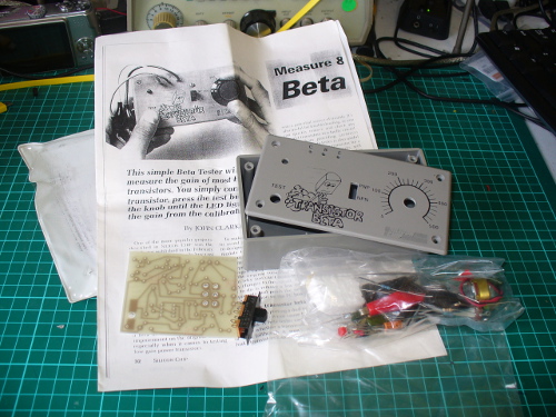 Continue reading →: Old Kit Review – Silicon Chip Transistor Beta Tester
Assembly of a classic Transistor Beta Tester kit from 1991
-
 Continue reading →: Arduino for Arduinians – 70 Projects for the Experienced Programmer
After helping tens of thousands of people get started with the world of electronics and Arduino-based microcontroller projects with the Arduino Workshop book, it was time to help and guide people further into more complex ideas and concepts that can enable a greater variety of possibilities. To make this possible…
-
 Continue reading →: Learn Microchip AVR Programming with “AVR Workshop A Hands-On Introduction with 60 Projects”
AVR Workshop is a comprehensive introduction to working with the Microchip AVR 8-bit family of microcontrollers – made famous through their use in Arduino and other compatible boards. Whether you’re an absolute beginner or longtime electronics enthusiast, this book gives you the latest coding and hardware knowledge required to build…
-
 Continue reading →: Announcing Arduino IDE 2.0
After a long period of development, we’re really happy to pass on the announcement that version 2.0.0 of the Arduino IDE is now available. Not only is it a more usable and practical development environment, there’s also some new features such as seamless cloud integration (which you are not forced…
-
 Continue reading →: Blinky the one-eyed Clock
This is a rewrite of a project I created in 2010 which brought me a lot of joy, so I hope you enjoy it too. Please read the entire article before starting your own. You can still make it today, the parts are easily available. I’ve always enjoyed making Arduino-powered…
-
 Continue reading →: Build a simple WFH Messaging System
Working from home – either you enjoy it, or doing so has been thrust upon you. As a world-class introvert I’ve always enjoyed being self-employed and working from my own office. However others do not, as they have missed out on the activity and interacting with other people in their…
-
 Continue reading →: Learn Arduino with “Arduino Workshop, 2nd Edition: A Hands-on Introduction with 65 Projects”
After eight years and much feedback from various readers, I’m proud to offer the second edition of my first book “Arduino Workshop”, from No Starch Press. This is a revised update to this very popular book which is aimed at any person who wants to make electronic devices using the…
-
 Continue reading →: A tiny tiny 0.49″ 64 x 32 Graphic I2C OLED Display with Arduino
Use a 0.49″ 64 x 32 Graphic I2C OLED Display with Arduino
-
 Continue reading →: Tutorial – Using the 0.96″ 80 x 160 Full Color IPS LCD Module with Arduino
Learn how to use the 0.96″ 80 x 160 Full Color IPS LCD Module from PMD Way with Arduino and compatible boards
Hello,
I’m John Boxall

Welcome to my website “tronixstuff”, a cosy corner of the internet dedicated to our world of electronics. Here, I invite you to join me on a journey of learning by that started in 2010. My amateur radio callsign is VK4JBX. The site is updated irregularly.
Join the fun…
Stay updated with the latest tutorials, reviews and other posts by joining our free newsletter.
Recent posts


This website participates in the Amazon Services LLC Associates Program, an affiliate advertising program designed to provide a means for us to earn fees by linking to Amazon.com and affiliated sites.
