Tag Archives: analog

Arduino Tutorials – Chapter 22 – the AREF pin

Learn how to measure smaller voltages with greater accuracy using your Arduino.

In this tutorial we’ll look at how you can measure smaller voltages with greater accuracy using the analogue input pins on your Arduino or compatible board in conjunction with the AREF pin. However first we’ll do some revision to get you up to speed. Please read this post entirely before working with AREF the first time.
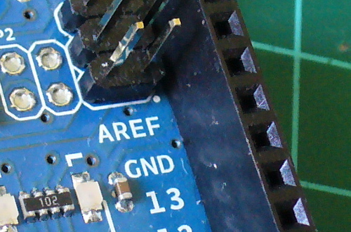
Arduino Uno from PMD Way

Revision

You may recall from the first few chapters in our series that we used the analogRead() function to measure the voltage of an electrical current from sensors and so on using one of the analogue input pins. The value returned from analogRead() would be between zero an 1023, with zero representing zero volts and 1023 representing the operating voltage of the Arduino board in use.

And when we say the operating voltage – this is the voltage available to the Arduino after the power supply circuitry. For example, if you have a typical Arduino Uno board and run it from the USB socket – sure, there is 5V available to the board from the USB socket on your computer or hub – but the voltage is reduced slightly as the current winds around the circuit to the microcontroller – or the USB source just isn’t up to scratch.

This can easily be demonstrated by connecting an Arduino Uno to USB and putting a multimeter set to measure voltage across the 5V and GND pins. Some boards will return as low as 4.8 V, some higher but still below 5V. So if you’re gunning for accuracy, power your board from an external power supply via the DC socket or Vin pin – such as 9V DC. Then after that goes through the power regulator circuit you’ll have a nice 5V, for example:
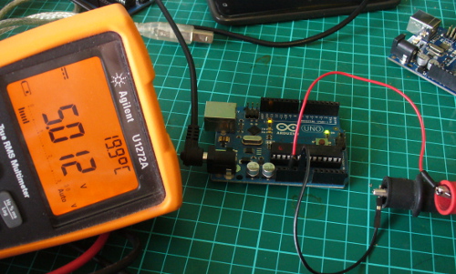
Arduino Uno from PMD Way

This is important as the accuracy of any analogRead() values will be affected by not having a true 5 V. If you don’t have any option, you can use some maths in your sketch to compensate for the drop in voltage. For example, if your voltage is 4.8V – the analogRead() range of 0~1023 will relate to 0~4.8V and not 0~5V. This may sound trivial, however if you’re using a sensor that returns a value as a voltage (e.g. the TMP36 temperature sensor) – the calculated value will be wrong. So in the interests of accuracy, use an external power supply.

Why does analogRead() return a value between 0 and 1023?

This is due to the resolution of the ADC. The resolution (for this article) is the degree to which something can be represented numerically. The higher the resolution, the greater accuracy with which something can be represented. We measure resolution in the terms of the number of bits of resolution.

For example, a 1-bit resolution would only allow two (two to the power of one) values – zero and one. A 2-bit resolution would allow four (two to the power of two) values – zero, one, two and three. If we tried to measure  a five volt range with a two-bit resolution, and the measured voltage was four volts, our ADC would return a numerical value of 3 – as four volts falls between 3.75 and 5V. It is easier to imagine this with the following image:

Arduino AREF

 So with our example ADC with 2-bit resolution, it can only represent the voltage with four possible resulting values. If the input voltage falls between 0 and 1.25, the ADC returns numerical 0; if the voltage falls between 1.25 and 2.5, the ADC returns a numerical value of 1. And so on. With our Arduino’s ADC range of 0~1023 – we have 1024 possible values – or 2 to the power of 10. So our Arduinos have an ADC with a 10-bit resolution.

So what is AREF? 

To cut a long story short, when your Arduino takes an analogue reading, it compares the voltage measured at the analogue pin being used against what is known as the reference voltage. In normal analogRead use, the reference voltage is the operating voltage of the board. For the more popular Arduino boards such as the Uno, Mega, Duemilanove and Leonardo/Yún boards, the operating voltage of 5V. If you have an Arduino Due board, the operating voltage is 3.3V. If you have something else – check the Arduino product page or ask your board supplier.

So if you have a reference voltage of 5V, each unit returned by analogRead() is valued at 0.00488 V. (This is calculated by dividing 1024 into 5V). What if we want to measure voltages between 0 and 2, or 0 and 4.6? How would the ADC know what is 100% of our voltage range?

And therein lies the reason for the AREF pin. AREF means Analogue REFerence. It allows us to feed the Arduino a reference voltage from an external power supply. For example, if we want to measure voltages with a maximum range of 3.3V, we would feed a nice smooth 3.3V into the AREF pin – perhaps from a voltage regulator IC. Then the each step of the ADC would represent around 3.22 millivolts (divide 1024 into 3.3).

Note that the lowest reference voltage you can have is 1.1V. There are two forms of AREF – internal and external, so let’s check them out.

External AREF

An external AREF is where you supply an external reference voltage to the Arduino board. This can come from a regulated power supply, or if you need 3.3V you can get it from the Arduino’s 3.3V pin. If you are using an external power supply, be sure to connect the GND to the Arduino’s GND pin. Or if you’re using the Arduno’s 3.3V source – just run a jumper from the 3.3V pin to the AREF pin.

To activate the external AREF, use the following in void setup():

analogReference(EXTERNAL); // use AREF for reference voltage

This sets the reference voltage to whatever you have connected to the AREF pin – which of course will have a voltage between 1.1V and the board’s operation voltage.

Very important note – when using an external voltage reference, you must set the analogue reference to EXTERNAL before using analogRead(). This will prevent you from shorting the active internal reference voltage and the AREF pin, which can damage the microcontroller on the board.

If necessary for your application, you can revert back to the board’s operating voltage for AREF (that is – back to normal) with the following:

analogReference(DEFAULT);

Now to demonstrate external AREF at work. Using a 3.3V AREF, the following sketch measures the voltage from A0 and displays the percentage of total AREF and the calculated voltage:

#include <LiquidCrystal.h>
LiquidCrystal lcd(8,9,4,5,6,7);

int analoginput = 0; // our analog pin
int analogamount = 0; // stores incoming value
float percentage = 0; // used to store our percentage value
float voltage =0; // used to store voltage value

void setup()
{
  lcd.begin(16, 2);
  analogReference(EXTERNAL); // use AREF for reference voltage
}

void loop()
{
  lcd.clear();
  analogamount=analogRead(analoginput);
  percentage=(analogamount/1024.00)*100;
  voltage=analogamount*3.222; // in millivolts
  lcd.setCursor(0,0);
  lcd.print("% of AREF: ");
  lcd.print(percentage,2);
  lcd.setCursor(0,1);  
  lcd.print("A0 (mV): ");
  lcd.println(voltage,2);
  delay(250);
}

The results of the sketch above are shown in the following video:

Internal AREF

The microcontrollers on our Arduino boards can also generate an internal reference voltage of 1.1V and we can use this for AREF work. Simply use the line:

analogReference(INTERNAL);

For Arduino Mega boards, use:

analogReference(INTERNAL1V1);

in void setup() and you’re off. If you have an Arduino Mega there is also a 2.56V reference voltage available which is activated with:

analogReference(INTERNAL2V56);

Finally – before settling on the results from your AREF pin, always calibrate the readings against a known good multimeter.

Conclusion

The AREF function gives you more flexibility with measuring analogue signals. If you are interested in using specific ADC components, we have tutorials on the ADS1110 16-bit ADC and the NXP PCF 8591 8-bit A/D and D/A IC.

This post brought to you by pmdway.com everything for makers and electronics enthusiasts, with free delivery worldwide.

To keep up to date with new posts at tronixstuff.com, please subscribe to the mailing list in the box on the right, or follow us on twitter @tronixstuff.

Tutorial – Arduino and PCF8591 ADC DAC IC

Have you ever wanted more analogue input pins on your Arduino project, but not wanted to fork out for a Mega? Or would you like to generate analogue signals? Then check out the subject of our tutorial – the NXP PCF8591 IC.

It solves both these problems as it has a single DAC (digital to analogue) converter as well as four ADCs (analogue to digital converters) – all accessible via the I2C bus. If the I2C bus is new to you, please familiarise yourself with the readings here before moving forward.

The PCF8591 is available in DIP, surface mount and module form, which makes it easy to experiment with:

PCF8591 from PMD Way

Before moving on, download the data sheet. The PCF8591 can operate on both 5V and 3.3V so if you’re using an Arduino Due, Raspberry Pi or other 3.3 V development board you’re fine. Now we’ll first explain the DAC, then the ADCs.

Using the DAC (digital-to-analogue converter)

The DAC on the PCF8591 has a resolution of 8-bits – so it can generate a theoretical signal of between zero volts and the reference voltage (Vref) in 255 steps. For demonstration purposes we’ll use a Vref of 5V, and you can use a lower Vref such as 3.3V or whatever you wish the maximum value to be … however it must be less than the supply voltage.

Note that when there is a load on the analogue output (a real-world situation), the maximum output voltage will drop – the data sheet (which you downloaded) shows a 10% drop for a 10kΩ load. Now for our demonstration circuit:

PCF8591 from PMD Way

Note the use of 10kΩ pull-up resistors on the I2C bus, and the 10μF capacitor between 5V and GND. The I2C bus address is set by a combination of pins A0~A2, and with them all to GND the address is 0x90. The analogue output can be taken from pin 15 (and there’s a seperate analogue GND on pin 13. Also, connect pin 13 to GND, and circuit GND to Arduino GND.

To control the DAC we need to send two bytes of data. The first is the control byte, which simply activates the DAC and is 1000000 (or 0x40) and the next byte is the value between 0 and 255 (the output level). This is demonstrated in the following sketch:

// Example 52.1 PCF8591 DAC demo
// https://tronixstuff.com/tutorials Chapter 52
// John Boxall June 2013
#include "Wire.h"
#define PCF8591 (0x90 >> 1) // I2C bus address
void setup()
{
 Wire.begin();
}
void loop()
{
 for (int i=0; i<256; i++)
 {
 Wire.beginTransmission(PCF8591); // wake up PCF8591
 Wire.write(0x40); // control byte - turn on DAC (binary 1000000)
 Wire.write(i); // value to send to DAC
 Wire.endTransmission(); // end tranmission
 }

 for (int i=255; i>=0; --i)
 {
 Wire.beginTransmission(PCF8591); // wake up PCF8591
 Wire.write(0x40); // control byte - turn on DAC (binary 1000000)
 Wire.write(i); // value to send to DAC
 Wire.endTransmission(); // end tranmission
 }
}

Did you notice the bit shift of the bus address in the #define statement? Arduino sends 7-bit addresses but the PCF8591 wants an 8-bit, so we shift the byte over by one bit. 

The results of the sketch are shown below, we’ve connected the Vref to 5V and the oscilloscope probe and GND to the analogue output and GND respectively:

PCF8591 from PMD Way

If you like curves you can generate sine waves with the sketch below. It uses a lookup table in an array which contains the necessary pre-calculated data points:

// Example 52.2 PCF8591 DAC demo - sine wave
// https://tronixstuff.com/tutorials Chapter 52
// John Boxall June 2013

#include "Wire.h"
#define PCF8591 (0x90 >> 1) // I2C bus address

uint8_t sine_wave[256] = {
 0x80, 0x83, 0x86, 0x89, 0x8C, 0x90, 0x93, 0x96,
 0x99, 0x9C, 0x9F, 0xA2, 0xA5, 0xA8, 0xAB, 0xAE,
 0xB1, 0xB3, 0xB6, 0xB9, 0xBC, 0xBF, 0xC1, 0xC4,
 0xC7, 0xC9, 0xCC, 0xCE, 0xD1, 0xD3, 0xD5, 0xD8,
 0xDA, 0xDC, 0xDE, 0xE0, 0xE2, 0xE4, 0xE6, 0xE8,
 0xEA, 0xEB, 0xED, 0xEF, 0xF0, 0xF1, 0xF3, 0xF4,
 0xF5, 0xF6, 0xF8, 0xF9, 0xFA, 0xFA, 0xFB, 0xFC,
 0xFD, 0xFD, 0xFE, 0xFE, 0xFE, 0xFF, 0xFF, 0xFF,
 0xFF, 0xFF, 0xFF, 0xFF, 0xFE, 0xFE, 0xFE, 0xFD,
 0xFD, 0xFC, 0xFB, 0xFA, 0xFA, 0xF9, 0xF8, 0xF6,
 0xF5, 0xF4, 0xF3, 0xF1, 0xF0, 0xEF, 0xED, 0xEB,
 0xEA, 0xE8, 0xE6, 0xE4, 0xE2, 0xE0, 0xDE, 0xDC,
 0xDA, 0xD8, 0xD5, 0xD3, 0xD1, 0xCE, 0xCC, 0xC9,
 0xC7, 0xC4, 0xC1, 0xBF, 0xBC, 0xB9, 0xB6, 0xB3,
 0xB1, 0xAE, 0xAB, 0xA8, 0xA5, 0xA2, 0x9F, 0x9C,
 0x99, 0x96, 0x93, 0x90, 0x8C, 0x89, 0x86, 0x83,
 0x80, 0x7D, 0x7A, 0x77, 0x74, 0x70, 0x6D, 0x6A,
 0x67, 0x64, 0x61, 0x5E, 0x5B, 0x58, 0x55, 0x52,
 0x4F, 0x4D, 0x4A, 0x47, 0x44, 0x41, 0x3F, 0x3C,
 0x39, 0x37, 0x34, 0x32, 0x2F, 0x2D, 0x2B, 0x28,
 0x26, 0x24, 0x22, 0x20, 0x1E, 0x1C, 0x1A, 0x18,
 0x16, 0x15, 0x13, 0x11, 0x10, 0x0F, 0x0D, 0x0C,
 0x0B, 0x0A, 0x08, 0x07, 0x06, 0x06, 0x05, 0x04,
 0x03, 0x03, 0x02, 0x02, 0x02, 0x01, 0x01, 0x01,
 0x01, 0x01, 0x01, 0x01, 0x02, 0x02, 0x02, 0x03,
 0x03, 0x04, 0x05, 0x06, 0x06, 0x07, 0x08, 0x0A,
 0x0B, 0x0C, 0x0D, 0x0F, 0x10, 0x11, 0x13, 0x15,
 0x16, 0x18, 0x1A, 0x1C, 0x1E, 0x20, 0x22, 0x24,
 0x26, 0x28, 0x2B, 0x2D, 0x2F, 0x32, 0x34, 0x37,
 0x39, 0x3C, 0x3F, 0x41, 0x44, 0x47, 0x4A, 0x4D,
 0x4F, 0x52, 0x55, 0x58, 0x5B, 0x5E, 0x61, 0x64,
 0x67, 0x6A, 0x6D, 0x70, 0x74, 0x77, 0x7A, 0x7D
};
void setup()
{
 Wire.begin();
}
void loop()
{
 for (int i=0; i<256; i++)
 {
 Wire.beginTransmission(PCF8591); // wake up PCF8591
 Wire.write(0x40); // control byte - turn on DAC (binary 1000000)
 Wire.write(sine_wave[i]); // value to send to DAC
 Wire.endTransmission(); // end tranmission
 }
}

And the results:

PCF8591 from PMD Way

For the following DSO image dump, we changed the Vref to 3.3V – note the change in the maxima on the sine wave:

PCF8591 from PMD Way

Now you can experiment with the DAC to make sound effects, signals or control other analogue circuits.

Using the ADCs (analogue-to-digital converters)

If you’ve used the analogRead() function on your Arduino (way back in Chapter One) then you’re already familiar with an ADC. With out PCF8591 we can read a voltage between zero and the Vref and it will return a value of between zero and 255 which is directly proportional to zero and the Vref.

For example, measuring 3.3V should return 168. The resolution (8-bit) of the ADC is lower than the onboard Arduino (10-bit) however the PCF8591 can do something the Arduino’s ADC cannot. But we’ll get to that in a moment.

First, to simply read the values of each ADC pin we send a control byte to tell the PCF8591 which ADC we want to read. For ADCs zero to three the control byte is 0x00, 0x01, ox02 and 0x03 respectively. Then we ask for two bytes of data back from the ADC, and store the second byte for use.

Why two bytes? The PCF8591 returns the previously measured value first – then the current byte. (See Figure 8 in the data sheet). Finally, if you’re not using all the ADC pins, connect the unused ones to GND.

The following example sketch simply retrieves values from each ADC pin one at a time, then displays them in the serial monitor:

// Example 52.3 PCF8591 ADC demo
// https://tronixstuff.com/tutorials Chapter 52
// John Boxall June 2013
#include "Wire.h"
#define PCF8591 (0x90 >> 1) // I2C bus address
#define ADC0 0x00 // control bytes for reading individual ADCs
#define ADC1 0x01
#define ADC2 0x02
#define ADC3 0x03
byte value0, value1, value2, value3;
void setup()
{
 Wire.begin();
 Serial.begin(9600);
}
void loop()
{
 Wire.beginTransmission(PCF8591); // wake up PCF8591
 Wire.write(ADC0); // control byte - read ADC0
 Wire.endTransmission(); // end tranmission
 Wire.requestFrom(PCF8591, 2);
 value0=Wire.read();
 value0=Wire.read();
 Wire.beginTransmission(PCF8591); // wake up PCF8591
 Wire.write(ADC1); // control byte - read ADC1
 Wire.endTransmission(); // end tranmission
 Wire.requestFrom(PCF8591, 2);
 value1=Wire.read();
 value1=Wire.read();
 Wire.beginTransmission(PCF8591); // wake up PCF8591
 Wire.write(ADC2); // control byte - read ADC2
 Wire.endTransmission(); // end tranmission
 Wire.requestFrom(PCF8591, 2);
 value2=Wire.read();
 value2=Wire.read();
 Wire.beginTransmission(PCF8591); // wake up PCF8591
 Wire.write(ADC3); // control byte - read ADC3
 Wire.endTransmission(); // end tranmission
 Wire.requestFrom(PCF8591, 2);
 value3=Wire.read();
 value3=Wire.read();
 Serial.print(value0); Serial.print(" ");
 Serial.print(value1); Serial.print(" ");
 Serial.print(value2); Serial.print(" ");
 Serial.print(value3); Serial.print(" ");
 Serial.println();
}

Upon running the sketch you’ll be presented with the values of each ADC in the serial monitor. Although it was a simple demonstration to show you how to individually read each ADC, it is a cumbersome method of getting more than one byte at a time from a particular ADC.

To do this, change the control byte to request auto-increment, which is done by setting bit 2 of the control byte to 1. So to start from ADC0 we use a new control byte of binary 00000100 or hexadecimal 0x04. Then request five bytes of data (once again we ignore the first byte) which will cause the PCF8591 to return all values in one chain of bytes. This process is demonstrated in the following sketch:

// Example 52.4 PCF8591 ADC demo
// https://tronixstuff.com/tutorials Chapter 52
// John Boxall June 2013
#include "Wire.h"
#define PCF8591 (0x90 >> 1) // I2C bus address
byte value0, value1, value2, value3;
void setup()
{
 Wire.begin();
 Serial.begin(9600);
}
void loop()
{
 Wire.beginTransmission(PCF8591); // wake up PCF8591
 Wire.write(0x04); // control byte - read ADC0 then auto-increment
 Wire.endTransmission(); // end tranmission
 Wire.requestFrom(PCF8591, 5);
 value0=Wire.read();
 value0=Wire.read();
 value1=Wire.read();
 value2=Wire.read();
 value3=Wire.read();
 Serial.print(value0); Serial.print(" ");
 Serial.print(value1); Serial.print(" ");
 Serial.print(value2); Serial.print(" ");
 Serial.print(value3); Serial.print(" ");
 Serial.println();
}

Previously we mentioned that the PCF8591 can do something that the Arduino’s ADC cannot, and this is offer a differential ADC. As opposed to the Arduino’s single-ended (i.e. it returns the difference between the positive signal voltage and GND, the differential ADC accepts two signals (that don’t necessarily have to be referenced to ground), and returns the difference between the two signals. This can be convenient for measuring small changes in voltages for load cells and so on.

Setting up the PCF8591 for differential ADC is a simple matter of changing the control byte. If you turn to page seven of the data sheet, then consider the different types of analogue input programming. Previously we used mode ’00’ for four inputs, however you can select the others which are clearly illustrated, for example:

PCF8591 from PMD Way

So to set the control byte for two differential inputs, use binary 00110000 or 0x30. Then it’s a simple matter of requesting the bytes of data and working with them. As you can see there’s also combination single/differential and a complex three-differential input. However we’ll leave them for the time being.

Conclusion

Hopefully you found this of interest, whether adding a DAC to your experiments or learning a bit more about ADCs. Please consider ordering your PCF8591 from PMD Way.

This post brought to you by pmdway.com – everything for makers and electronics enthusiasts, with free delivery worldwide.

To keep up to date with new posts at tronixstuff.com, please subscribe to the mailing list in the box on the right, or follow us on twitter @tronixstuff.

Tutorial: Video output from your Arduino

In this tutorial we will examine something different – the ability of our Arduino and compatible boards to create composite video output. In other words, displaying stuff from the Arduino on a TV with analog video input.

A lot of people were unaware of the ability to do this, however the process is very simple and not difficult to implement from a hardware perspective. Within this chapter we will learn to construct the minimum hardware required and demonstrate basic functions to get started.

To whet your appetite, here is a quick video demonstration of what is possible:

You can’t expect too much from a 16 MHz microcontroller without a video card… but the price is right, and with some imagination and the right functions you can do quite well. To make this happen we need to knock out some hardware of our own.

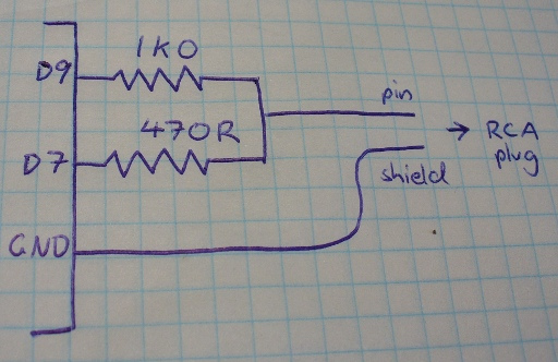
Connection is very easy. First we need to locate three pins on our Arduino board. They will be used to output Sync, Video and also GND. For those with Arduino Uno, etc – Sync is digital 9, video is digital 7 and GND is … GND. If you have a Mega/Mega2560 Sync is digital 11 and video is A7. There is also the ability to generate audio with the methods in this article, and if you want to do this the Uno (etc.) pin is digital 11 or 10 on the Mega.

The monitor or television used needs to have a composite video-in socket (jack). For those with older televisions that have a VCR connected, you could use the video-in socket on the VCR. The schematic for video out is very simple, you only need two normal 0.25W resistors and a video lead:

basicschem

If you’re not up for soldering into an RCA plug, a simple way is to chop up a standard video lead as such:

cablestripss

Then just wire the termination of the two resistors to the centre core (“pin”) and GND to the shield. For the purpose of this article we have made a quick TV-out shield that also includes a thumb joystick.

mshieldss

A real triumph of engineering… however it solves the problem. The vertical trimmer is connected to A0;  the horizontal to A1; the button to digital 8 via a 10k0 pull-up resistor. Next, you will need to download and install the arduino-tvout library. It can be found here. We will use the TVoutBeta1.zip version.  Those of you who may have a nootropic design Hackvision – please note your library is different.

Now to see how to integrate TV-out into our sketch. We will run through the basic functions which integrated with your imagination should see some interesting results…  So let’s go!

For every project, place these two lines at the top of your sketch:

#include "TVout.h"
TVout TV;

The first brings in the library, and the second line creates an instance of TV to use with the library functions. Next, we need to activate TVout and select the appropriate broadcast standard (PAL or NTSC). In void setup() use either

TV.start_render(_NTSC) // for NTSC (or)
TV.start_render(_PAL); // for PAL system

Now for the main functions. The first one of interest will be:

TV.clear_screen();

which … clears the screen. Or if you would like to fill the screen with white, use

TV.fill_screen(1);

Moving on – to write some text. First we need to select a font. There are three basic fonts to choose from:

  • font4x6 (each character being 4 pixels by 6 pixels, etc.)
  • font6x8
  • font8x8

Well there is four, but it wouldn’t display for me. Working on it! To choose a font use:

TV.select_font(font4x6); // using font4x6

Then to write the text, choose the screen location with:

TV.set_cursor(x,y);

then display the text with:

TV.print("Hello, world..."); // etc

You can also use TV.println(); to add a carriage return as expected. Display single characters with a position in the one function using:

TV.print_char(x,y,c); // c is the character to display

So let’s have a look at the various fonts in action with the following sketch:


Now to move into the 1970s with some basic graphical functions. We have a screen resolution of 128 by 96 pixels to work with. When planning your display, you need to ensure that the sketch never attempts to display a pixel outside of the 128 x 96 screen area. Doing so generally causes the Arduino to reboot.

First let’s start with basic pixels. To draw a pixel, use:
TV.set_pixel(x,y,z);

where x and y are the coordinates of the pixel, and z is the colour (1 = white, 0 = black, 2 = inverse of current pixel’s colour). You want more than a pixel? How about a line:

TV.draw_line(x1,y1,x2,y2,colour);

Draws a line from x1, y1 to x2, y2 of colour colour. (1 = white, 0 = black, 2 = inverse of current pixel’s colour).

Rectangles? Easy:

TV.draw_rect(x,y,w,h,colour,fill);

Draws a rectangle with the top-left corner at x,y; width w, height h, colour and optional fill colour. Circles are just as simple:

TV.draw_circle(x,y,r,colour,fill);

Draws a circle with centre at x,y; radius r pixels, edge colour, optional fill colour.

Now to see these functions in action with the following sketch:

/*
  arduino-tvout text demonstration
 */

#include <TVout.h>
#include <fontALL.h>
TVout TV;

int d=10; // for delay purposes
char c='X';

void setup()
{
  TV.begin(_PAL); // for PAL system
  TV.clear_screen();
}

void loop()
{
  TV.select_font(font4x6);
  for (int a=0; a<6; a++)
  {
    for (int b=0; b<128; b++)
    {
      TV.print_char(b,a*6,c);
      delay(d);
      TV.clear_screen();
    }
  }
  delay(1000);
  TV.clear_screen();  

  TV.select_font(font6x8);
  for (int a=0; a<6; a++)
  {
    for (int b=0; b<128; b++)
    {
      TV.print_char(b,a*8,c);
      delay(d);  
      TV.clear_screen();
    }
  }
  delay(1000);
  TV.clear_screen();  

  TV.select_font(font8x8);
  for (int a=0; a<6; a++)
  {
    for (int b=0; b<128; b++)
    {
      TV.print_char(b,a*8,c);
      delay(d);  
      TV.clear_screen();
    }
  }
  delay(1000);
  TV.clear_screen();  
}

And for the video demonstration:

So there you have it, a start with Arduino and TV-out. Furthermore, a big thanks to http://code.google.com/u/mdmetzle/ for the arduino-tvout library.

This post brought to you by pmdway.com everything for makers and electronics enthusiasts, with free delivery worldwide.

To keep up to date with new posts at tronixstuff.com, please subscribe to the mailing list in the box on the right, or follow us on twitter @tronixstuff.