
In this first of several tutorials we are going to investigate the I2C data bus, and how we can control devices using it with our Arduino systems. The I2C bus can be a complex interface to master, so we will do my best to simplify it for you.
In this article we will learn the necessary theory, and then apply it by controlling a variety of devices. Furthermore it would be in your interest to have an understanding of the binary, binary-coded decimal and hexadecimal number systems.
But first of all, what is it?
I2C is an acronym for “Inter-Integrated Circuit”. In the late 1970s, Philips’ semiconductor division (now NXP) saw the need for simplifying and standardising the data lines that travel between various integrated circuits in their products.
Their solution was the I2C bus. This reduced the number of wires to two (SDA – data, and SCL – clock). Here is a nice introductory video from NXP:
Why would we want to use I2C devices?
As there are literally thousands of components that use the I2C interface. And our Arduino boards can control them all. There are many applications, such a real-time clocks, digital potentiometers, temperature sensors, digital compasses, memory chips, FM radio circuits, I/O expanders, LCD controllers, amplifiers, and so on.
And you can have more than one on the bus at any time, in fact the maximum number of I2C devices used at any one time is 112.
From a hardware perspective, the wiring is very easy. Those of you with an Arduino Uno or 100% compatible board, you will be using pins A4 for SDA (data) and A5 for SCL (clock):

If you are using an Arduino Mega, SDA is pin 20 and SCL is 21, so note that shields with I2C need to be specifically for the Mega. If you have another type of board, check your data sheet or try the Arduino team’s hardware website.
And finally, if you are using a bare DIP ATmega328 microcontroller, you will use pins 27 for SDA and 28 for SCL. The bus wiring is simple:

If you are only using one I2C device, the pull-up resistors are (normally) not required, as the ATmega328 microcontroller in our Arduino has them built-in. However if you are running a string of devices, use two 10 kilo ohm resistors.
Like anything, some testing on a breadboard or prototype circuit will determine their necessity. Sometimes you may see in a particular device’s data sheet the use of different value pull-up resistors – for example 4.7k ohm.
If so, heed that advice. The maximum length of an I2C bus is around one metre, and is a function of the capacitance of the bus. This distance can be extended with the use of a special IC, which we will examine during the next I2C chapter.
Each device can be connected to the bus in any order, and devices can be masters or slaves. In our Arduino situation, the board is the master and the devices on the I2C bus are the slaves.
We can write data to a device, or read data from a device. By now you should be thinking “how do we differentiate each device on the bus?”… Each device has a unique address. We use that address in the functions described later on to direct our read or write requests to the correct device.
It is possible to use two devices with identical addresses on an I2C bus, but that will be discussed in a later article.
As like most devices, we make use of an Arduino library, in this case <wire.h>. Then use the function Wire.begin(); inside of void setup() and we’re ready to go.
Sending data from our Arduino to the I2C devices requires two things: the unique device address (we need this in hexadecimal) and at least one byte of data to send. For example, the address of the part in example 20.1 (below) is 00101111 (binary) which is 0X2F in hexadecimal. Then we want to set the wiper value, which is a value between 0 and 127, or 0x00 and 0x7F in hexadecimal. So to set the wiper to zero, we would use the following three functions:
Wire.beginTransmission(0x2F); // part address is 0x2F or 0101111
This sends the device address down the SDA (data) line of the bus. It travels along the bus, and “notifies” the matching device that it has some data coming…
Wire.write(0); // sends 0 down the bus
This sends the byte of data to the device – into the device register (or memory of sorts), which is waiting for it with open arms. Any other devices on the bus will ignore this.
Note that you can only perform one I2C operation at a time! Then when we have finished sending data to the device, we “end transmission”. This tells the device that we’re finished, and frees up the I2C bus for the next operation:
Wire.endTransmission();
Some devices may have more than one register, and require more bytes of data in each transmission. For example, the DS1307 real-time clock IC has eight registers to store timing data, each requiring eight bits of data (one byte):

However with the DS1307 – the entire lot need to be rewritten every time. So in this case we would use eight wire.send(); functions every time. Each device will interpret the byte of data sent to it, so you need the data sheet for your device to understand how to use it.
Receiving data from an I2C device into our Arduino requires two things: the unique device address (we need this in hexadecimal) and the number of bytes of data to accept from the device.
Receiving data at this point is a two stage process. If you review the table above from the DS1307 data sheet, note that there is eight registers, or bytes of data in there. The first thing we need to do is have the I2C device start reading from the first register, which is done by sending a zero to the device:
Wire.beginTransmission(device_address);
Wire.write(0);
Wire.endTransmission();
Now the I2C device will send data from the first register when requested. We now need to ask the device for the data, and how many bytes we want. For example, if a device held three bytes of data, we would ask for three, and store each byte in its own variable (for example, we have three variables of type byte: a, b, and c. The first function to execute is:
Wire.requestFrom(device_address, 3);
Which tells the device to send three bytes of data back to the Arduino. We then immediately follow this with:
*a = Wire.read();
*b = Wire.read();
*c = Wire.read();
We do not need to use Wire.endTransmission() when reading data. Now that the requested data is in their respective variables, you can treat them like any ordinary byte variable. For a more detailed explanation of the I2C bus, read this explanatory document by NXP. Now let’s use our I2C knowledge by controlling a range of devices…
The Microchip MCP4018T digital linear potentiometer. The value of this model is 10 kilo ohms. Inside this tiny, tiny SMD part is a resistor array consisting of 127 elements and a wiper that we control by sending a value of between 0 and 127 (in hexadecimal) down the I2C bus. This is a volatile digital potentiometer, it forgets the wiper position when the power is removed.
However naturally there is a compromise with using such a small part, it is only rated for 2.5 milliamps – but used in conjunction with op amps and so on. For more information, please consult the data sheet. As this is an SMD part, for breadboard prototyping purposes it needed to be mounted on a breakout board. Here it is in raw form:
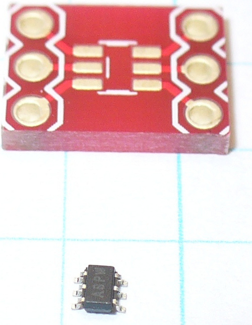
Above the IC is a breakout board. Consider that the graph paper is 5mm square! It is the incorrect size, but all I have. However soldering was bearable. Put a drop of solder on one pad of the breakout board, then hold the IC with tweezers in one hand, and reheat the solder with the other hand – then push the IC into place. A few more tiny blobs of solder over the remaining pins, and remove the excess with solder wick. Well … it worked for me:

Our example schematic is as follows:

As you can see, the part is simple to use, your signal enters pin 6 and the result of the voltage division is found on pin 5. Please note that this is not a replacement for a typical mechanical potentiometer, we can’t just hook this up as a volume or motor-speed control! Again, please read the data sheet.
Control is very simple, we only need to send one byte of data down, the hexadecimal reference point for the wiper, e.g.:
Wire.beginTransmission(0x2F);      // part address is 0x2F or 0101111b
Wire.write(0x3F); //
Wire.endTransmission();
Here is a quick demonstration that moves the wiper across all points:
int dt = 2000; // used for delay duration
byte rval = 0x00; // used for value sent to potentiometer
#include "Wire.h"
#define pot_address 0x2F // each I2C object has a unique bus address, the MCP4018 is 0x2F or 0101111 in binary

void setup()
{
  Wire.begin();
  Serial.begin(9600);
}

void potLoop()
// sends values of 0x00 to 0x7F to pot in order to change the resistance
// equates to 0~127
{
  for (rval=0; rval<128; rval++)
  {
    Wire.beginTransmission(pot_address);
    Wire.write(rval); //
    Wire.endTransmission();
    Serial.print(" sent - ");
    Serial.println(rval, HEX);
    delay(dt);
  }
}

void loop()
{
  potLoop();
}
and a video demonstration:
Now we will read some data from an I2C device. Our test subject is the ST Microelectronics CN75 temperature sensor. Again, we have another SMD component, but the CN75 is the next stage larger than the part from example 20.1. Thankfully this makes the soldering process much easier, however still requiring some delicate handiwork:
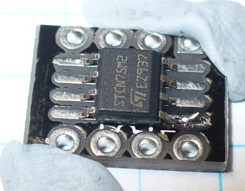
First, a small blob of solder, then slide the IC into it. Once that has cooled, you can complete the rest and solder the header pins into the breakout board:

Our example schematic is as follows:

Pins 5, 6 and 7 determine the final three bits of the device address – in this case they are all set to GND, which sets the address to 1001000. This allows you to use multiple sensors on the same bus. Pin 3 is not used for basic temperature use, however it is an output for the thermostat functions, which we will examine in the next chapter.
As a thermometer it can return temperatures down to the nearest half of a degree Celsius. Although that may not be accurate enough, it was designed for automotive and thermostat use. For more details please read the data sheet. The CN75 stores the temperature data in two bytes, let’s call them A and B. So we use
Wire.requestFrom(cn75address, 2)
with the second parameter as 2, as we want two bytes of data. Which we then store using the following functions:
*a = Wire.read(); // first received byte stored here
*b = Wire.read(); // second received byte stored here
where *a and *b are variables of the type byte. And as always, there is a twist to decoding the temperature from these bytes. Here are two example pieces of sample data:
Example bytes one: 00011001 10000000
Example bytes two: 11100111 00000000
The bits in each byte note particular values… the most significant bit (leftmost) of byte A determines whether it is below or above zero degrees – 1 for below zero. The remaining seven bits are the binary representation of the integer part of the temperature; if it is below zero, we subtract 128 from the value of the whole byte and multiply by -1.
The most significant bit of byte B determines the fraction, either zero or half a degree. So as you will see in the following example sketch, there is some decision making done in showCN75data():
#include "Wire.h"
#define cn75address 0x48 // with pins 5~7 set to GND, the device address is 0x48

void setup()
{
  Wire.begin(); // wake up I2C bus
  Serial.begin(9600);
}

void getCN75data(byte *a, byte *b)
{
  // move the register pointer back to the first register
  Wire.beginTransmission(cn75address); // "Hey, CN75 @ 0x48! Message for you"
  Wire.write(0); // "move your register pointer back to 00h"
  Wire.endTransmission(); // "Thanks, goodbye..."
  // now get the data from the CN75
  Wire.requestFrom(cn75address, 2); // "Hey, CN75 @ 0x48 - please send me the contents of your first two registers"
  *a = Wire.read(); // first received byte stored here
  *b = Wire.read(); // second received byte stored here
}

void showCN75data()
{
  byte aa,bb;
  float temperature=0;
  getCN75data(&aa,&bb);
  if (aa>127) // check for below zero degrees
  {
    temperature=((aa-128)*-1);
    if (bb==128) // check for 0.5 fraction
    {
      temperature-=0.5;
    }
  }
  else // it must be above zero degrees
  {
    temperature=aa;
    if (bb==128) // check for 0.5 fraction
    {
      temperature+=0.5;
    }
  }
  Serial.print("Temperature = ");
  Serial.print(temperature,1);
  Serial.println(" degrees C");
  delay(1000);
}

void loop()
{
  showCN75data();
}
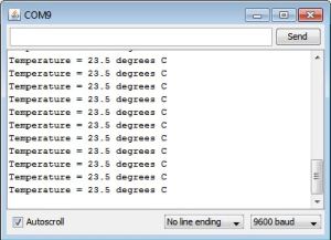
And here is the result from the serial monitor:

Now that we know how to read and write data to devices on the I2C bus – here is an example of doing both, with a very popular device – the Maxim DS1307 real-time clock IC. Before moving on, consider reading their good data sheet.
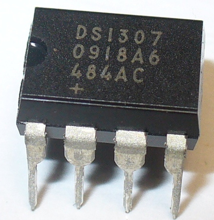
Furthermore, it also has a programmable square-wave generator. Connection and use is quite simple:

However some external components are required: a 32.768 kHz crystal, a 3V battery for time retention when the power is off, and a 10k ohm pullup resistor is required if using as a square-wave generator, and 10k ohm pull-up resistors on the SCL and SDA lines.
To save building the circuit up yourself, you can order a neat module.
You can use the SQW and timing simultaneously. If we have a more detailed look at the register map for the DS1307:
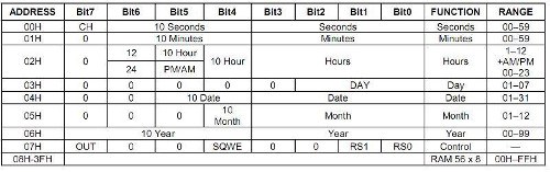
We see that the first seven registers are for timing data, the eighth is the square-wave control, and then another eight RAM registers. In this chapter we will look at the first eight only. Hopefully you have noticed that various time parameters are represented by less than eight bits of data – the DS1307 uses binary-coded decimal. But don’t panic, we have some functions to do the conversions for us.
However, in general – remember that each bit in each register can only be zero or one – so how do we represent a register’s contents in hexadecimal? First, we need to find the binary representation, then convert that to hexadecimal.
So, using the third register of the DS1307 as an example, and a time of 12:34 pm – we will read from left to right. Bit 7 is unused, so it is 0. Bit 6 determines whether the time kept is 12- or 24-hour time. So we’ll choose 1 for 12-hour time. Bit 5 (when bit 6 is 0) is the AM/PM indicator – choose 1 for PM. Bit 4 represents the left-most digit of the time, that is the 1 in 12:34 pm. So we’ll choose 1. Bits 3 to 0 represent the BCD version of 2 which is 0010.
So to store 12pm as hours we need to write 00110010 as hexadecimal into the hours register – which is 0x32. Reading data from the DS1307 should be easy for you now, reset the register pointed, then request seven bytes of data and receive them into seven variables. The device address is 0x68. For example:
Wire.beginTransmission(0x68);
Wire.write(0);
Wire.endTransmission();
Wire.requestFrom(DS1307_I2C_ADDRESS, 7);
*second     = bcdToDec(Wire.read();
*minute     = bcdToDec(Wire.read();
*hour       = bcdToDec(Wire.read();
*dayOfWeek  = bcdToDec(Wire.read());
*dayOfMonth = bcdToDec(Wire.read());
*month      = bcdToDec(Wire.read());
*year       = bcdToDec(Wire.read());
At which point the time data will need to be converted to decimal numbers, which we will take care of in the example sketch later. Setting the time, or controlling the square-wave output is another long operation – you need to write seven variables to set the time or eight to change the square-wave output. For example, the time:
Wire.beginTransmission(0x68);
Wire.write(0);
Wire.write(decToBcd(second));
Wire.write(decToBcd(minute));
Wire.write(decToBcd(hour));
Wire.write(decToBcd(dayOfWeek));
Wire.write(decToBcd(dayOfMonth));
Wire.write(decToBcd(month));
Wire.write(decToBcd(year));
Wire.endTransmission();
The decToBcd is a function defined in our example to convert the decimal numbers to BCD suitable for the DS1307.
You can also address each register individually. We will demonstrate doing this with an explanation of how to control the DS1037’s in built square-wave generator:
/*
DS1307 Square-wave machine
 Used to demonstrate the four different square-wave outputs from Maxim DS1307
 See DS1307 data sheet for more information
 */

#include "Wire.h"
#define DS1307_I2C_ADDRESS 0x68 // each I2C object has a unique bus address, the DS1307 is 0x68

void setup()
{
 Wire.begin();
}

void sqw1() // set to 1Hz
{
 Wire.beginTransmission(DS1307_I2C_ADDRESS);
 Wire.write(0x07); // move pointer to SQW address
 Wire.write(0x10); // sends 0x10 (hex) 00010000 (binary)
 Wire.endTransmission();
}

void sqw2() // set to 4.096 kHz
{
 Wire.beginTransmission(DS1307_I2C_ADDRESS);
 Wire.write(0x07); // move pointer to SQW address
 Wire.write(0x11); // sends 0x11 (hex) 00010001 (binary)
 Wire.endTransmission();
}

void sqw3() // set to 8.192 kHz
{
 Wire.beginTransmission(DS1307_I2C_ADDRESS);
 Wire.write(0x07); // move pointer to SQW address
 Wire.write(0x12); // sends 0x12 (hex) 00010010 (binary)
 Wire.endTransmission();
}

void sqw4() // set to 32.768 kHz (the crystal frequency)
{
 Wire.beginTransmission(DS1307_I2C_ADDRESS);
 Wire.write(0x07); // move pointer to SQW address
 Wire.write(0x13); // sends 0x13 (hex) 00010011 (binary)
 Wire.endTransmission();
}

void sqwOff()
// turns the SQW off
{
 Wire.beginTransmission(DS1307_I2C_ADDRESS);
 Wire.write(0x07); // move pointer to SQW address
 Wire.write(0x00); // turns the SQW pin off
 Wire.endTransmission();
}

void loop()
{
 sqw1();
 delay(5000);
 sqw2();
 delay(5000);
 sqw3();
 delay(5000);
 sqw4();
 delay(5000);
 sqwOff();
 delay(5000);
}
Here is the SQW output in action – we measure the frequency using our very old Tek CFC-250:
For further DS1307 examples, we will not repeat ourselves and instead direct you to the list of many tronixstuff articles that make use of the DS1307.
So there you have it – hopefully an easy to understand introduction to the world of the I2C bus and how to control the devices within. Part two of the I2C tutorial has now been published, as well as an article about the NXP SAA1064 LED display driver IC and the Microchip MC23017 16-bit port expander IC.
I hope you enjoyed reading about the I2C bus. If you find this sort of thing interesting, please consider ordering one or more of my books from amazon.
To keep up to date with new posts at tronixstuff.com, please subscribe to the mailing list in the box on the right, or follow us on x – @tronixstuff.
And as always, have fun and make something.


You must be logged in to post a comment.