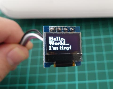
In this article we look at the tiny 0.49″ 64×32 graphic OLED from PMD Way. It is a compact and useful display, that only requires a small amount of time to get working with your Arduino or compatible board.
The purpose of this guide is to get your display successfully operating with your Arduino, so you can move forward and experiment and explore further types of operation with the display.
This includes installing the Arduino library, making a succesful board connection and running a demonstration sketch. So let’s get started!
Connecting the display to your Arduino
The display uses the I2C data bus for communication, and is a 5V and 3.3V-tolerant board.
Arduino Uno to Display
GND ---- GND (GND)

5V/3.3V- Vcc (power supply, can be 3.3V or 5V)

A5 ----- SCL (I2C bus clock)

A4 ----- SDA (I2C bus data)
I2C pinouts vary for other boards. Arduino Leonard uses D2/D3 for SDA and SCL or the separate pins to the left of D13. Arduino Mega uses D20/D21 for SDA and SCL. If you can’t find your I2C pins on other boards, email admin at tronixstuff dot com for assistance.
Installing the Arduino library
To install the library – simply open the Arduino IDE and select Manage Libraries… from the Tools menu. Enter “u8g2” in the search box, and after a moment it should appear in the results as shown in the image below. Click on the library then click “Install”:
After a moment the library will be installed and you can close that box.
Now it’s time to check everything necessary is working. Open a new sketch in the IDE, then copy and paste the following sketch into the IDE (you may find the “view raw” link at the end useful):
This file contains bidirectional Unicode text that may be interpreted or compiled differently than what appears below. To review, open the file in an editor that reveals hidden Unicode characters. Learn more about bidirectional Unicode characters
Your display should go through the demonstration of various font sizes and so on as shown in the video below:
You can see how we’ve used a different font in the sketch – at lines 19, 30 and 38. The list of fonts included with the library are provided at https://github.com/olikraus/u8g2/wiki/fntlistall.
Note that the initial location for each line of text (for example in line 20):
u8g2.drawStr(0, 5, "Hello,"); // write something to the internal memory
The x and y coordinates (0,5) are for the bottom-left of the first character.
If you want to display values, not text – such as integers, use:
u8g2.print();
… an example of which is show around line 49 in the example sketch.
Where to from here?
Now it’s time for you to explore the library reference guide which explains all the various functions available to create text and graphics on the display, as well as the fonts and so on. These can all be found on the right-hand side of the driver wiki page.
And that’s all for now. This post brought to you by pmdway.com – everything for makers and electronics enthusiasts, with free delivery worldwide.
To keep up to date with new posts at tronixstuff.com, please subscribe to the mailing list in the box on the right, or follow us on twitter @tronixstuff.
The purpose of this guide is to get your 0.96″ color LCD display successfully operating with your Arduino, so you can move forward and experiment and explore further types of operation with the display. This includes installing the Arduino library, making a succesful board connection and running a demonstration sketch.
Although you can use the display with an Arduino Uno or other boad with an ATmega328-series microcontroller – this isn’t recommended for especially large projects. The library eats up a fair amount of flash memory – around 60% in most cases.
So if you’re running larger projects we recommend using an Arduino Mega or Due-compatible board due to the increased amount of flash memory in their host microcontrollers.
Installing the Arduino library
So let’s get started. We’ll first install the Arduino library then move on to hardware connection and then operating the display.
(As the display uses the ST7735S controller IC, you may be tempted to use the default TFT library included with the Arduino IDE – however it isn’t that reliable. Instead, please follow the instructions below).
First – download the special Arduino library for your display and save it into your Downloads or a temp folder.
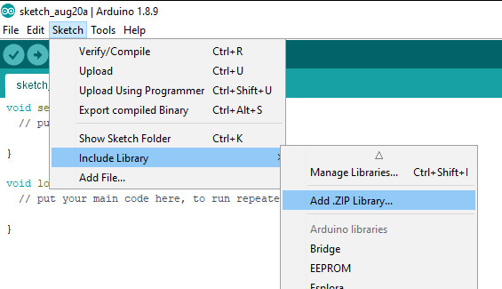
Next – open the Arduino IDE and select the Sketch > Include Library > Add .ZIP library option as shown below:
A dialog box will open – navigate to and select the zip file you downloaded earlier. After a moment or two the IDE will then install the library.
Please check that the library has been installed – to do this, select the Sketch > Include Library option in the IDE and scroll down the long menu until you see “ER-TFTM0.96-1” as shown below:
Once that has been successful, you can wire up your display.
Connecting the display to your Arduino
The display uses the SPI data bus for communication, and is a 3.3V board. You can use it with an Arduino or other 5V board as the logic is tolerant of higher voltages.
Arduino to Display
GND ----- GND (GND)

3.3V ---- Vcc (3.3V power supply)

D13 ----- SCL (SPI bus clock)

D11 ----- SDA (SPI bus data out from Arduino)

D10 ----- CS (SPI bus "Chip Select")

D9 ------ DC (Data instruction select pin)

D8 ------ RES (reset input)
If your Arduino has different pinouts than the Uno, locate the SPI pins for your board and modify as appropriate.
Demonstration sketch
Open a new sketch in the IDE, then copy and paste the following sketch into the IDE:
// https://pmdway.com/products/0-96-80-x-160-full-color-lcd-module#include<UTFT.h>// Declare which fonts we will be usingexternuint8_tSmallFont[];// Initialize display// Library only supports software SPI at this time//NOTE: support DUE , MEGA , UNO //SDI=11 SCL=13 /CS =10 /RST=8 D/C=9UTFTmyGLCD(ST7735S_4L_80160,11,13,10,8,9);//LCD: 4Line serial interface SDI SCL /CS /RST D/C NOTE:Only support DUE MEGA UNO// Declare which fonts we will be usingexternuint8_tBigFont[];intcolor=0;wordcolorlist[]={VGA_WHITE,VGA_BLACK,VGA_RED,VGA_BLUE,VGA_GREEN,VGA_FUCHSIA,VGA_YELLOW,VGA_AQUA};intbsize=4;voiddrawColorMarkerAndBrushSize(intcol){myGLCD.setColor(VGA_BLACK);myGLCD.fillRect(25,0,31,239);myGLCD.fillRect(myGLCD.getDisplayXSize()-31,161,myGLCD.getDisplayXSize()-1,191);myGLCD.setColor(VGA_WHITE);myGLCD.drawPixel(25,(col*30)+15);for(inti=1;i<7;i++)myGLCD.drawLine(25+i,((col*30)+15)-i,25+i,((col*30)+15)+i);if(color==1)myGLCD.setColor(VGA_WHITE);elsemyGLCD.setColor(colorlist[col]);if(bsize==1)myGLCD.drawPixel(myGLCD.getDisplayXSize()-15,177);elsemyGLCD.fillCircle(myGLCD.getDisplayXSize()-15,177,bsize);myGLCD.setColor(colorlist[col]);}voidsetup(){randomSeed(analogRead(0));// Setup the LCDmyGLCD.InitLCD();myGLCD.setFont(SmallFont);}voidloop(){intbuf[158];intx,x2;inty,y2;intr;// Clear the screen and draw the framemyGLCD.clrScr();myGLCD.setColor(255,0,0);myGLCD.fillRect(0,0,159,13);myGLCD.setColor(64,64,64);myGLCD.fillRect(0,114,159,127);myGLCD.setColor(255,255,255);myGLCD.setBackColor(255,0,0);myGLCD.print("pmdway.com.",CENTER,1);myGLCD.setBackColor(64,64,64);myGLCD.setColor(255,255,0);myGLCD.print("pmdway.com",LEFT,114);myGLCD.setColor(0,0,255);myGLCD.drawRect(0,13,159,113);// Draw crosshairsmyGLCD.setColor(0,0,255);myGLCD.setBackColor(0,0,0);myGLCD.drawLine(79,14,79,113);myGLCD.drawLine(1,63,158,63);myGLCD.setColor(0,0,255);myGLCD.drawLine(0,79,159,79);for(inti=9;i<150;i+=10)myGLCD.drawLine(i,61,i,65);for(inti=19;i<110;i+=10)myGLCD.drawLine(77,i,81,i);// Draw sin-, cos- and tan-lines myGLCD.setColor(0,255,255);myGLCD.print("Sin",5,15);for(inti=1;i<158;i++){myGLCD.drawPixel(i,63+(sin(((i*2.27)*3.14)/180)*40));}myGLCD.setColor(255,0,0);myGLCD.print("Cos",5,27);for(inti=1;i<158;i++){myGLCD.drawPixel(i,63+(cos(((i*2.27)*3.14)/180)*40));}myGLCD.setColor(255,255,0);myGLCD.print("Tan",5,39);for(inti=1;i<158;i++){myGLCD.drawPixel(i,63+(tan(((i*2.27)*3.14)/180)));}delay(2000);myGLCD.setColor(0,0,0);myGLCD.fillRect(1,14,158,113);myGLCD.setColor(0,0,255);myGLCD.setBackColor(0,0,0);myGLCD.drawLine(79,14,79,113);myGLCD.drawLine(1,63,158,63);myGLCD.setColor(0,0,255);myGLCD.drawLine(0,79,159,79);// Draw a moving sinewavex=1;for(inti=1;i<(158*20);i++){x++;if(x==159)x=1;if(i>159){if((x==79)||(buf[x-1]==63))myGLCD.setColor(0,0,255);elsemyGLCD.setColor(0,0,0);myGLCD.drawPixel(x,buf[x-1]);}myGLCD.setColor(0,255,255);y=63+(sin(((i*2.5)*3.14)/180)*(40-(i/100)));myGLCD.drawPixel(x,y);buf[x-1]=y;}delay(2000);myGLCD.setColor(0,0,0);myGLCD.fillRect(1,14,158,113);myGLCD.setColor(0,0,255);myGLCD.drawLine(0,79,159,79);// Draw some filled rectanglesfor(inti=1;i<6;i++){switch(i){case1:myGLCD.setColor(255,0,255);break;case2:myGLCD.setColor(255,0,0);break;case3:myGLCD.setColor(0,255,0);break;case4:myGLCD.setColor(0,0,255);break;case5:myGLCD.setColor(255,255,0);break;}myGLCD.fillRect(39+(i*10),23+(i*10),59+(i*10),43+(i*10));}delay(2000);myGLCD.setColor(0,0,0);myGLCD.fillRect(1,14,158,113);myGLCD.setColor(0,0,255);myGLCD.drawLine(0,79,159,79);// Draw some filled, rounded rectanglesfor(inti=1;i<6;i++){switch(i){case1:myGLCD.setColor(255,0,255);break;case2:myGLCD.setColor(255,0,0);break;case3:myGLCD.setColor(0,255,0);break;case4:myGLCD.setColor(0,0,255);break;case5:myGLCD.setColor(255,255,0);break;}myGLCD.fillRoundRect(99-(i*10),23+(i*10),119-(i*10),43+(i*10));}delay(2000);myGLCD.setColor(0,0,0);myGLCD.fillRect(1,14,158,113);myGLCD.setColor(0,0,255);myGLCD.drawLine(0,79,159,79);// Draw some filled circlesfor(inti=1;i<6;i++){switch(i){case1:myGLCD.setColor(255,0,255);break;case2:myGLCD.setColor(255,0,0);break;case3:myGLCD.setColor(0,255,0);break;case4:myGLCD.setColor(0,0,255);break;case5:myGLCD.setColor(255,255,0);break;}myGLCD.fillCircle(49+(i*10),33+(i*10),15);}delay(2000);myGLCD.setColor(0,0,0);myGLCD.fillRect(1,14,158,113);myGLCD.setColor(0,0,255);myGLCD.drawLine(0,79,159,79);// Draw some lines in a patternmyGLCD.setColor(255,0,0);for(inti=14;i<113;i+=5){myGLCD.drawLine(1,i,(i*1.44)-10,112);}myGLCD.setColor(255,0,0);for(inti=112;i>15;i-=5){myGLCD.drawLine(158,i,(i*1.44)-12,14);}myGLCD.setColor(0,255,255);for(inti=112;i>15;i-=5){myGLCD.drawLine(1,i,172-(i*1.44),14);}myGLCD.setColor(0,255,255);for(inti=15;i<112;i+=5){myGLCD.drawLine(158,i,171-(i*1.44),112);}delay(2000);myGLCD.setColor(0,0,0);myGLCD.fillRect(1,14,158,113);myGLCD.setColor(0,0,255);myGLCD.drawLine(0,79,159,79);// Draw some random circlesfor(inti=0;i<100;i++){myGLCD.setColor(random(255),random(255),random(255));x=22+random(116);y=35+random(57);r=random(20);myGLCD.drawCircle(x,y,r);}delay(2000);myGLCD.setColor(0,0,0);myGLCD.fillRect(1,14,158,113);myGLCD.setColor(0,0,255);myGLCD.drawLine(0,79,159,79);// Draw some random rectanglesfor(inti=0;i<100;i++){myGLCD.setColor(random(255),random(255),random(255));x=2+random(156);y=16+random(95);x2=2+random(156);y2=16+random(95);myGLCD.drawRect(x,y,x2,y2);}delay(2000);myGLCD.setColor(0,0,0);myGLCD.fillRect(1,14,158,113);myGLCD.setColor(0,0,255);myGLCD.drawLine(0,79,159,79);// Draw some random rounded rectanglesfor(inti=0;i<100;i++){myGLCD.setColor(random(255),random(255),random(255));x=2+random(156);y=16+random(95);x2=2+random(156);y2=16+random(95);myGLCD.drawRoundRect(x,y,x2,y2);}delay(2000);myGLCD.setColor(0,0,0);myGLCD.fillRect(1,14,158,113);myGLCD.setColor(0,0,255);myGLCD.drawLine(0,79,159,79);for(inti=0;i<100;i++){myGLCD.setColor(random(255),random(255),random(255));x=2+random(156);y=16+random(95);x2=2+random(156);y2=16+random(95);myGLCD.drawLine(x,y,x2,y2);}delay(2000);myGLCD.setColor(0,0,0);myGLCD.fillRect(1,14,158,113);myGLCD.setColor(0,0,255);myGLCD.drawLine(0,79,159,79);for(inti=0;i<5000;i++){myGLCD.setColor(random(255),random(255),random(255));myGLCD.drawPixel(2+random(156),16+random(95));}delay(2000);myGLCD.fillScr(0,0,255);myGLCD.setColor(255,0,0);myGLCD.fillRoundRect(10,17,149,72);myGLCD.setColor(255,255,255);myGLCD.setBackColor(255,0,0);myGLCD.print("That's it!",CENTER,20);myGLCD.print("Restarting in a",CENTER,45);myGLCD.print("few seconds...",CENTER,57);myGLCD.setColor(0,255,0);myGLCD.setBackColor(0,0,255);myGLCD.print("Runtime: (msecs)",CENTER,103);myGLCD.printNumI(millis(),CENTER,115);delay(5000);}
Once you’re confident with the physical connection, upload the sketch. It should result with output as shown in the video below:
Now that you have succesfully run the demonstration sketch – where to from here?
The library used is based on the uTFT library by Henning Karlsen. You can find all the drawing and other commands in the user manual – so download the pdf and enjoy creating interesting displays.
This post brought to you by pmdway.com – everything for makers and electronics enthusiasts, with free delivery worldwide.
To keep up to date with new posts at tronixstuff.com, please subscribe to the mailing list in the box on the right, or follow us on twitter @tronixstuff.
The purpose of this guide is to have an SSD1306-based OLED display successfully operating with your Arduino, so you can move forward and experiment and explore further types of operation with the display.
This includes installing the Arduino library, making a succesful board connection and running a demonstration sketch. So let’s get started!
Connecting the display to your Arduino
The display uses the I2C data bus for communication, and is a 5V and 3.3V-tolerant board.
Arduino Uno to Display
GND ---- GND (GND)

5V/3.3V- Vcc (power supply, can be 3.3V or 5V)

A5 ----- SCL (I2C bus clock)

A4 ----- SDA (I2C bus data)
I2C pinouts vary for other boards. Arduino Leonard uses D2/D3 for SDA and SCL or the separate pins to the left of D13. Arduino Mega uses D20/D21 for SDA and SCL. If you can’t find your I2C pins on other boards, ask your display supplier.
Installing the Arduino library
To install the library – simply open the Arduino IDE and select Manage Libraries… from the Tools menu. Enter “u8g2” in the search box, and after a moment it should appear in the results as shown in the image below. Click on the library then click “Install”:
After a moment the library will be installed and you can close that box.
Now it’s time to check everything necessary is working. Open a new sketch in the IDE, then copy and paste the following sketch into the IDE:
// Display > https://pmdway.com/products/0-96-128-64-graphic-oled-displays-i2c-or-spi-various-colors#include<Arduino.h>#include<U8x8lib.h>#ifdefU8X8_HAVE_HW_SPI#include<SPI.h>#endif#ifdefU8X8_HAVE_HW_I2C#include<Wire.h>#endifU8X8_SSD1306_128X64_NONAME_HW_I2Cu8x8(/* reset=*/U8X8_PIN_NONE);/* This example will probably not work with the SSD1606, because of the internal buffer swapping*/voidsetup(void){/* U8g2 Project: KS0108 Test Board *///pinMode(16, OUTPUT);//digitalWrite(16, 0); /* U8g2 Project: Pax Instruments Shield: Enable Backlight *///pinMode(6, OUTPUT);//digitalWrite(6, 0); u8x8.begin();//u8x8.setFlipMode(1);}voidpre(void){u8x8.setFont(u8x8_font_amstrad_cpc_extended_f);u8x8.clear();u8x8.inverse();u8x8.print(" U8x8 Library ");u8x8.setFont(u8x8_font_chroma48medium8_r);u8x8.noInverse();u8x8.setCursor(0,1);}voiddraw_bar(uint8_tc,uint8_tis_inverse){uint8_tr;u8x8.setInverseFont(is_inverse);for(r=0;r<u8x8.getRows();r++){u8x8.setCursor(c,r);u8x8.print(" ");}}voiddraw_ascii_row(uint8_tr,intstart){inta;uint8_tc;for(c=0;c<u8x8.getCols();c++){u8x8.setCursor(c,r);a=start+c;if(a<=255)u8x8.write(a);}}voidloop(void){inti;uint8_tc,r,d;pre();u8x8.print("github.com/");u8x8.setCursor(0,2);u8x8.print("olikraus/u8g2");delay(2000);u8x8.setCursor(0,3);u8x8.print("Tile size:");u8x8.print((int)u8x8.getCols());u8x8.print("x");u8x8.print((int)u8x8.getRows());delay(2000);pre();for(i=19;i>0;i--){u8x8.setCursor(3,2);u8x8.print(i);u8x8.print(" ");delay(150);}draw_bar(0,1);for(c=1;c<u8x8.getCols();c++){draw_bar(c,1);draw_bar(c-1,0);delay(50);}draw_bar(u8x8.getCols()-1,0);pre();u8x8.setFont(u8x8_font_amstrad_cpc_extended_f);for(d=0;d<8;d++){for(r=1;r<u8x8.getRows();r++){draw_ascii_row(r,(r-1+d)*u8x8.getCols()+32);}delay(400);}draw_bar(u8x8.getCols()-1,1);for(c=u8x8.getCols()-1;c>0;c--){draw_bar(c-1,1);draw_bar(c,0);delay(50);}draw_bar(0,0);pre();u8x8.drawString(0,2,"Small");u8x8.draw2x2String(0,5,"Scale Up");delay(3000);pre();u8x8.drawString(0,2,"Small");u8x8.setFont(u8x8_font_px437wyse700b_2x2_r);u8x8.drawString(0,5,"2x2 Font");delay(3000);pre();u8x8.drawString(0,1,"3x6 Font");u8x8.setFont(u8x8_font_inb33_3x6_n);for(i=0;i<100;i++){u8x8.setCursor(0,2);u8x8.print(i);// Arduino Print functiondelay(10);}for(i=0;i<100;i++){u8x8.drawString(0,2,u8x8_u16toa(i,5));// U8g2 Build-In functionsdelay(10);}pre();u8x8.drawString(0,2,"Weather");u8x8.setFont(u8x8_font_open_iconic_weather_4x4);for(c=0;c<6;c++){u8x8.drawGlyph(0,4,'@'+c);delay(300);}pre();u8x8.print("print \\n\n");delay(500);u8x8.println("println");delay(500);u8x8.println("done");delay(1500);pre();u8x8.fillDisplay();for(r=0;r<u8x8.getRows();r++){u8x8.clearLine(r);delay(100);}delay(1000);}
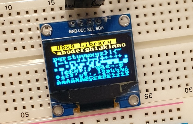
Your display should go through the demonstration of various things as shown in the video below:
If the display did not work – you may need to manually set the I2C bus address. To do this, wire up your OLED then run this sketch (open the serial monitor for results). It’s an I2C scanner tool that will return the I2C bus display.
Then use the following line in void setup():
u8x8.setI2CAddress(address)
Replace u8x8 with your display reference, and address with the I2C bus address (for example. 0x17).
Moving on…
By now you have an idea of what is possible with these great-value displays.
Now your display is connected and working, it’s time to delve deeper into the library and the various modes of operations. There are three, and they are described in the library documentation – click here to review them.
Whenever you use one of the three modes mentioned above, you need to use one of the following constructor lines:
U8G2_SSD1306_128X64_NONAME_F_HW_I2C u8g2(U8G2_R0, /* reset=*/ U8X8_PIN_NONE); // full buffer mode
U8X8_SSD1306_128X64_NONAME_HW_I2C u8x8(/* reset=*/ U8X8_PIN_NONE); // 8x8 character mode
Match the mode you wish to use with one of the constructors above. For example, in the demonstration sketch you ran earlier, we used the 8×8 character mode constructor in line 14.
Where to from here?
Now it’s time for you to explore the library reference guide which explains all the various functions available to create text and graphics on the display, as well as the fonts and so on. These can all be found on the right-hand side of the driver wiki page.
This post brought to you by pmdway.com – everything for makers and electronics enthusiasts, with free delivery worldwide.
To keep up to date with new posts at tronixstuff.com, please subscribe to the mailing list in the box on the right, or follow us on twitter @tronixstuff.
We keep getting requests on how to use DS1307 and DS3231 real-time clock modules with Arduino from various sources – so this is the first of a two part tutorial on how to use them. For this Arduino tutorial we have two real-time clock modules to use, one based on the Maxim DS1307:
There are two main differences between the ICs on the real-time clock modules, which is the accuracy of the time-keeping. The DS1307 used in the first module works very well, however the external temperature can affect the frequency of the oscillator circuit which drives the DS1307’s internal counter.
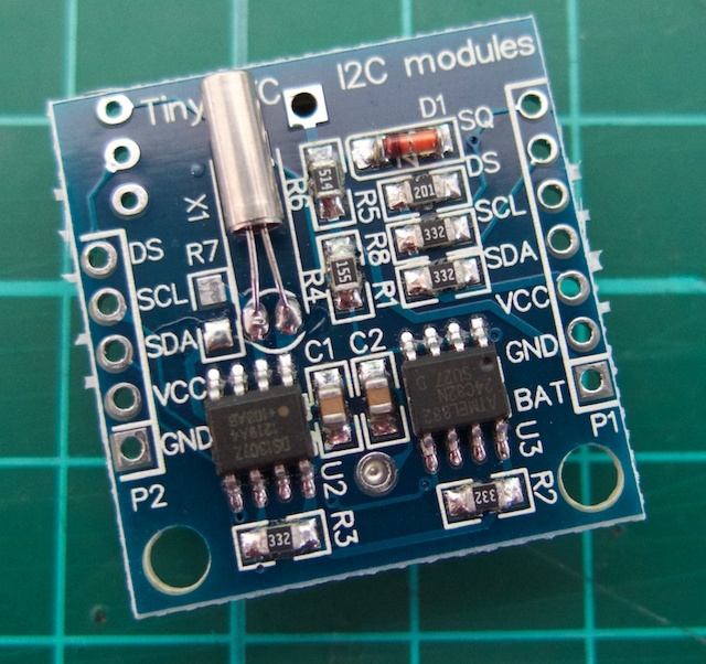
This may sound like a problem, however will usually result with the clock being off by around five or so minutes per month. The DS3231 is much more accurate, as it has an internal oscillator which isn’t affected by external factors – and thus is accurate down to a few minutes per year at the most. If you have a DS1307 module- don’t feel bad, it’s still a great value board and will serve you well.
With both of the modules, a backup battery is not installed when you receive them – it’s a good idea to buy a new CR2032 battery and fit it to the module.
Along with keeping track of the time and date, these modules also have a small EEPROM, an alarm function (DS3231 only) and the ability to generate a square-wave of various frequencies – all of which will be the subject of a second tutorial.
Connecting your module to an Arduino
Both modules use the I2C bus, which makes connection very easy. If you’re not sure about the I2C bus and Arduino, check out the I2C tutorials (chapters 20 and 21), or review chapter seventeen of the book “Arduino Workshop“.
Moving on – first you will need to identify which pins on your Arduino or compatible boards are used for the I2C bus – these will be knows as SDA (or data) and SCL (or clock).
On Arduino Uno or compatible boards, these pins are A4 and A5 for data and clock;
On the Arduino Mega the pins are D20 and D21 for data and clock;
And if you’re using a Pro Mini-compatible the pins are A4 and A5 for data and clock, which are parallel to the main pins.
DS1307 module
If you have the DS1307 module you will need to solder the wires to the board, or solder on some inline header pins so you can use jumper wires. Then connect the SCL and SDA pins to your Arduino, and the Vcc pin to the 5V pin and GND to GND.
DS3231 module
Connecting this module is easy as header pins are installed on the board at the factory. You can simply run jumper wires again from SCL and SDA to the Arduino and again from the module’s Vcc and GND pins to your board’s 5V or 3.3.V and GND. However these are duplicated on the other side for soldering your own wires.
Both of these modules have the required pull-up resistors, so you don’t need to add your own. Like all devices connected to the I2C bus, try and keep the length of the SDA and SCL wires to a minimum.
Reading and writing the time from your RTC Module
Once you have wired up your RTC module. enter and upload the following sketch. Although the notes and functions in the sketch refer only to the DS3231, the code also works with the DS1307.
#include "Wire.h"
#define DS3231_I2C_ADDRESS 0x68
// Convert normal decimal numbers to binary coded decimal
byte decToBcd(byte val)
{
  return( (val/10*16) + (val%10) );
}
// Convert binary coded decimal to normal decimal numbers
byte bcdToDec(byte val)
{
  return( (val/16*10) + (val%16) );
}
void setup()
{
  Wire.begin();
  Serial.begin(9600);
  // set the initial time here:
  // DS3231 seconds, minutes, hours, day, date, month, year
  // setDS3231time(30,42,21,4,26,11,14);
}
void setDS3231time(byte second, byte minute, byte hour, byte dayOfWeek, byte
dayOfMonth, byte month, byte year)
{
  // sets time and date data to DS3231
  Wire.beginTransmission(DS3231_I2C_ADDRESS);
  Wire.write(0); // set next input to start at the seconds register
  Wire.write(decToBcd(second)); // set seconds
  Wire.write(decToBcd(minute)); // set minutes
  Wire.write(decToBcd(hour)); // set hours
  Wire.write(decToBcd(dayOfWeek)); // set day of week (1=Sunday, 7=Saturday)
  Wire.write(decToBcd(dayOfMonth)); // set date (1 to 31)
  Wire.write(decToBcd(month)); // set month
  Wire.write(decToBcd(year)); // set year (0 to 99)
  Wire.endTransmission();
}
void readDS3231time(byte *second,
byte *minute,
byte *hour,
byte *dayOfWeek,
byte *dayOfMonth,
byte *month,
byte *year)
{
  Wire.beginTransmission(DS3231_I2C_ADDRESS);
  Wire.write(0); // set DS3231 register pointer to 00h
  Wire.endTransmission();
  Wire.requestFrom(DS3231_I2C_ADDRESS, 7);
  // request seven bytes of data from DS3231 starting from register 00h
  *second = bcdToDec(Wire.read() & 0x7f);
  *minute = bcdToDec(Wire.read());
  *hour = bcdToDec(Wire.read() & 0x3f);
  *dayOfWeek = bcdToDec(Wire.read());
  *dayOfMonth = bcdToDec(Wire.read());
  *month = bcdToDec(Wire.read());
  *year = bcdToDec(Wire.read());
}
void displayTime()
{
  byte second, minute, hour, dayOfWeek, dayOfMonth, month, year;
  // retrieve data from DS3231
  readDS3231time(&second, &minute, &hour, &dayOfWeek, &dayOfMonth, &month,
  &year);
  // send it to the serial monitor
  Serial.print(hour, DEC);
  // convert the byte variable to a decimal number when displayed
  Serial.print(":");
  if (minute<10)
  {
    Serial.print("0");
  }
  Serial.print(minute, DEC);
  Serial.print(":");
  if (second<10)
  {
    Serial.print("0");
  }
  Serial.print(second, DEC);
  Serial.print(" ");
  Serial.print(dayOfMonth, DEC);
  Serial.print("/");
  Serial.print(month, DEC);
  Serial.print("/");
  Serial.print(year, DEC);
  Serial.print(" Day of week: ");
  switch(dayOfWeek){
  case 1:
    Serial.println("Sunday");
    break;
  case 2:
    Serial.println("Monday");
    break;
  case 3:
    Serial.println("Tuesday");
    break;
  case 4:
    Serial.println("Wednesday");
    break;
  case 5:
    Serial.println("Thursday");
    break;
  case 6:
    Serial.println("Friday");
    break;
  case 7:
    Serial.println("Saturday");
    break;
  }
}
void loop()
{
  displayTime(); // display the real-time clock data on the Serial Monitor,
  delay(1000); // every second
}
There may be a lot of code, however it breaks down well into manageable parts.
It first includes the Wire library, which is used for I2C bus communication, followed by defining the bus address for the RTC as 0x68. These are followed by two functions that convert decimal numbers to BCD (binary-coded decimal) and vice versa. These are necessary as the RTC ICs work in BCD not decimal.
The function setDS3231time() is used to set the clock. Using it is very easy, simple insert the values from year down to second, and the RTC will start from that time. For example if you want to set the following date and time – Wednesday November 26, 2014 and 9:42 pm and 30 seconds – you would use:
setDS3231time(30,42,21,4,26,11,14);
Note that the time is set using 24-hour time, and the fourth paramter is the “day of week”. This falls between 1 and 7 which is Sunday to Saturday respectively. These parameters are byte values if you are subsituting your own variables.
Once you have run the function once it’s wise to prefix it with // and upload your code again, so it will not reset the time once the power has been cycled or micrcontroller reset.
Reading the time form your RTC Is just as simple, in fact the process can be followed neatly inside the function displayTime(). You will need to define seven byte variables to store the data from the RTC, and these are then inserted in the function readDS3231time().
Then you can use the variables as you see fit, from sending the time and date to the serial monitor as the example sketch does – to converting the data into a suitable form for all sorts of output devices.
Just to check everything is working, enter the appropriate time and date into the demonstration sketch, upload it, comment out the setDS3231time() function and upload it again. Then open the serial monitor, and you should be provided with a running display of the current time and date.
From this point you now have the software tools to set data to and retrieve it from your real-time clock module, and we hope you have an understanding of how to use these inexpensive modules.
You can learn more about the particular real-time clock ICs from the manufacturer’s website – DS1307 and DS3231.
This post brought to you by pmdway.com everything for makers and electronics enthusiasts, with free delivery worldwide.
To keep up to date with new posts at tronixstuff.com, please subscribe to the mailing list in the box on the right, or follow us on twitter @tronixstuff.


You must be logged in to post a comment.