Category Archives: education

Tutorial – Arduino and PCF8591 ADC DAC IC

Have you ever wanted more analogue input pins on your Arduino project, but not wanted to fork out for a Mega? Or would you like to generate analogue signals? Then check out the subject of our tutorial – the NXP PCF8591 IC.

It solves both these problems as it has a single DAC (digital to analogue) converter as well as four ADCs (analogue to digital converters) – all accessible via the I2C bus. If the I2C bus is new to you, please familiarise yourself with the readings here before moving forward.

The PCF8591 is available in DIP, surface mount and module form, which makes it easy to experiment with:

PCF8591 from PMD Way

Before moving on, download the data sheet. The PCF8591 can operate on both 5V and 3.3V so if you’re using an Arduino Due, Raspberry Pi or other 3.3 V development board you’re fine. Now we’ll first explain the DAC, then the ADCs.

Using the DAC (digital-to-analogue converter)

The DAC on the PCF8591 has a resolution of 8-bits – so it can generate a theoretical signal of between zero volts and the reference voltage (Vref) in 255 steps. For demonstration purposes we’ll use a Vref of 5V, and you can use a lower Vref such as 3.3V or whatever you wish the maximum value to be … however it must be less than the supply voltage.

Note that when there is a load on the analogue output (a real-world situation), the maximum output voltage will drop – the data sheet (which you downloaded) shows a 10% drop for a 10kΩ load. Now for our demonstration circuit:

PCF8591 from PMD Way

Note the use of 10kΩ pull-up resistors on the I2C bus, and the 10μF capacitor between 5V and GND. The I2C bus address is set by a combination of pins A0~A2, and with them all to GND the address is 0x90. The analogue output can be taken from pin 15 (and there’s a seperate analogue GND on pin 13. Also, connect pin 13 to GND, and circuit GND to Arduino GND.

To control the DAC we need to send two bytes of data. The first is the control byte, which simply activates the DAC and is 1000000 (or 0x40) and the next byte is the value between 0 and 255 (the output level). This is demonstrated in the following sketch:

// Example 52.1 PCF8591 DAC demo
// https://tronixstuff.com/tutorials Chapter 52
// John Boxall June 2013
#include "Wire.h"
#define PCF8591 (0x90 >> 1) // I2C bus address
void setup()
{
 Wire.begin();
}
void loop()
{
 for (int i=0; i<256; i++)
 {
 Wire.beginTransmission(PCF8591); // wake up PCF8591
 Wire.write(0x40); // control byte - turn on DAC (binary 1000000)
 Wire.write(i); // value to send to DAC
 Wire.endTransmission(); // end tranmission
 }

 for (int i=255; i>=0; --i)
 {
 Wire.beginTransmission(PCF8591); // wake up PCF8591
 Wire.write(0x40); // control byte - turn on DAC (binary 1000000)
 Wire.write(i); // value to send to DAC
 Wire.endTransmission(); // end tranmission
 }
}

Did you notice the bit shift of the bus address in the #define statement? Arduino sends 7-bit addresses but the PCF8591 wants an 8-bit, so we shift the byte over by one bit. 

The results of the sketch are shown below, we’ve connected the Vref to 5V and the oscilloscope probe and GND to the analogue output and GND respectively:

PCF8591 from PMD Way

If you like curves you can generate sine waves with the sketch below. It uses a lookup table in an array which contains the necessary pre-calculated data points:

// Example 52.2 PCF8591 DAC demo - sine wave
// https://tronixstuff.com/tutorials Chapter 52
// John Boxall June 2013

#include "Wire.h"
#define PCF8591 (0x90 >> 1) // I2C bus address

uint8_t sine_wave[256] = {
 0x80, 0x83, 0x86, 0x89, 0x8C, 0x90, 0x93, 0x96,
 0x99, 0x9C, 0x9F, 0xA2, 0xA5, 0xA8, 0xAB, 0xAE,
 0xB1, 0xB3, 0xB6, 0xB9, 0xBC, 0xBF, 0xC1, 0xC4,
 0xC7, 0xC9, 0xCC, 0xCE, 0xD1, 0xD3, 0xD5, 0xD8,
 0xDA, 0xDC, 0xDE, 0xE0, 0xE2, 0xE4, 0xE6, 0xE8,
 0xEA, 0xEB, 0xED, 0xEF, 0xF0, 0xF1, 0xF3, 0xF4,
 0xF5, 0xF6, 0xF8, 0xF9, 0xFA, 0xFA, 0xFB, 0xFC,
 0xFD, 0xFD, 0xFE, 0xFE, 0xFE, 0xFF, 0xFF, 0xFF,
 0xFF, 0xFF, 0xFF, 0xFF, 0xFE, 0xFE, 0xFE, 0xFD,
 0xFD, 0xFC, 0xFB, 0xFA, 0xFA, 0xF9, 0xF8, 0xF6,
 0xF5, 0xF4, 0xF3, 0xF1, 0xF0, 0xEF, 0xED, 0xEB,
 0xEA, 0xE8, 0xE6, 0xE4, 0xE2, 0xE0, 0xDE, 0xDC,
 0xDA, 0xD8, 0xD5, 0xD3, 0xD1, 0xCE, 0xCC, 0xC9,
 0xC7, 0xC4, 0xC1, 0xBF, 0xBC, 0xB9, 0xB6, 0xB3,
 0xB1, 0xAE, 0xAB, 0xA8, 0xA5, 0xA2, 0x9F, 0x9C,
 0x99, 0x96, 0x93, 0x90, 0x8C, 0x89, 0x86, 0x83,
 0x80, 0x7D, 0x7A, 0x77, 0x74, 0x70, 0x6D, 0x6A,
 0x67, 0x64, 0x61, 0x5E, 0x5B, 0x58, 0x55, 0x52,
 0x4F, 0x4D, 0x4A, 0x47, 0x44, 0x41, 0x3F, 0x3C,
 0x39, 0x37, 0x34, 0x32, 0x2F, 0x2D, 0x2B, 0x28,
 0x26, 0x24, 0x22, 0x20, 0x1E, 0x1C, 0x1A, 0x18,
 0x16, 0x15, 0x13, 0x11, 0x10, 0x0F, 0x0D, 0x0C,
 0x0B, 0x0A, 0x08, 0x07, 0x06, 0x06, 0x05, 0x04,
 0x03, 0x03, 0x02, 0x02, 0x02, 0x01, 0x01, 0x01,
 0x01, 0x01, 0x01, 0x01, 0x02, 0x02, 0x02, 0x03,
 0x03, 0x04, 0x05, 0x06, 0x06, 0x07, 0x08, 0x0A,
 0x0B, 0x0C, 0x0D, 0x0F, 0x10, 0x11, 0x13, 0x15,
 0x16, 0x18, 0x1A, 0x1C, 0x1E, 0x20, 0x22, 0x24,
 0x26, 0x28, 0x2B, 0x2D, 0x2F, 0x32, 0x34, 0x37,
 0x39, 0x3C, 0x3F, 0x41, 0x44, 0x47, 0x4A, 0x4D,
 0x4F, 0x52, 0x55, 0x58, 0x5B, 0x5E, 0x61, 0x64,
 0x67, 0x6A, 0x6D, 0x70, 0x74, 0x77, 0x7A, 0x7D
};
void setup()
{
 Wire.begin();
}
void loop()
{
 for (int i=0; i<256; i++)
 {
 Wire.beginTransmission(PCF8591); // wake up PCF8591
 Wire.write(0x40); // control byte - turn on DAC (binary 1000000)
 Wire.write(sine_wave[i]); // value to send to DAC
 Wire.endTransmission(); // end tranmission
 }
}

And the results:

PCF8591 from PMD Way

For the following DSO image dump, we changed the Vref to 3.3V – note the change in the maxima on the sine wave:

PCF8591 from PMD Way

Now you can experiment with the DAC to make sound effects, signals or control other analogue circuits.

Using the ADCs (analogue-to-digital converters)

If you’ve used the analogRead() function on your Arduino (way back in Chapter One) then you’re already familiar with an ADC. With out PCF8591 we can read a voltage between zero and the Vref and it will return a value of between zero and 255 which is directly proportional to zero and the Vref.

For example, measuring 3.3V should return 168. The resolution (8-bit) of the ADC is lower than the onboard Arduino (10-bit) however the PCF8591 can do something the Arduino’s ADC cannot. But we’ll get to that in a moment.

First, to simply read the values of each ADC pin we send a control byte to tell the PCF8591 which ADC we want to read. For ADCs zero to three the control byte is 0x00, 0x01, ox02 and 0x03 respectively. Then we ask for two bytes of data back from the ADC, and store the second byte for use.

Why two bytes? The PCF8591 returns the previously measured value first – then the current byte. (See Figure 8 in the data sheet). Finally, if you’re not using all the ADC pins, connect the unused ones to GND.

The following example sketch simply retrieves values from each ADC pin one at a time, then displays them in the serial monitor:

// Example 52.3 PCF8591 ADC demo
// https://tronixstuff.com/tutorials Chapter 52
// John Boxall June 2013
#include "Wire.h"
#define PCF8591 (0x90 >> 1) // I2C bus address
#define ADC0 0x00 // control bytes for reading individual ADCs
#define ADC1 0x01
#define ADC2 0x02
#define ADC3 0x03
byte value0, value1, value2, value3;
void setup()
{
 Wire.begin();
 Serial.begin(9600);
}
void loop()
{
 Wire.beginTransmission(PCF8591); // wake up PCF8591
 Wire.write(ADC0); // control byte - read ADC0
 Wire.endTransmission(); // end tranmission
 Wire.requestFrom(PCF8591, 2);
 value0=Wire.read();
 value0=Wire.read();
 Wire.beginTransmission(PCF8591); // wake up PCF8591
 Wire.write(ADC1); // control byte - read ADC1
 Wire.endTransmission(); // end tranmission
 Wire.requestFrom(PCF8591, 2);
 value1=Wire.read();
 value1=Wire.read();
 Wire.beginTransmission(PCF8591); // wake up PCF8591
 Wire.write(ADC2); // control byte - read ADC2
 Wire.endTransmission(); // end tranmission
 Wire.requestFrom(PCF8591, 2);
 value2=Wire.read();
 value2=Wire.read();
 Wire.beginTransmission(PCF8591); // wake up PCF8591
 Wire.write(ADC3); // control byte - read ADC3
 Wire.endTransmission(); // end tranmission
 Wire.requestFrom(PCF8591, 2);
 value3=Wire.read();
 value3=Wire.read();
 Serial.print(value0); Serial.print(" ");
 Serial.print(value1); Serial.print(" ");
 Serial.print(value2); Serial.print(" ");
 Serial.print(value3); Serial.print(" ");
 Serial.println();
}

Upon running the sketch you’ll be presented with the values of each ADC in the serial monitor. Although it was a simple demonstration to show you how to individually read each ADC, it is a cumbersome method of getting more than one byte at a time from a particular ADC.

To do this, change the control byte to request auto-increment, which is done by setting bit 2 of the control byte to 1. So to start from ADC0 we use a new control byte of binary 00000100 or hexadecimal 0x04. Then request five bytes of data (once again we ignore the first byte) which will cause the PCF8591 to return all values in one chain of bytes. This process is demonstrated in the following sketch:

// Example 52.4 PCF8591 ADC demo
// https://tronixstuff.com/tutorials Chapter 52
// John Boxall June 2013
#include "Wire.h"
#define PCF8591 (0x90 >> 1) // I2C bus address
byte value0, value1, value2, value3;
void setup()
{
 Wire.begin();
 Serial.begin(9600);
}
void loop()
{
 Wire.beginTransmission(PCF8591); // wake up PCF8591
 Wire.write(0x04); // control byte - read ADC0 then auto-increment
 Wire.endTransmission(); // end tranmission
 Wire.requestFrom(PCF8591, 5);
 value0=Wire.read();
 value0=Wire.read();
 value1=Wire.read();
 value2=Wire.read();
 value3=Wire.read();
 Serial.print(value0); Serial.print(" ");
 Serial.print(value1); Serial.print(" ");
 Serial.print(value2); Serial.print(" ");
 Serial.print(value3); Serial.print(" ");
 Serial.println();
}

Previously we mentioned that the PCF8591 can do something that the Arduino’s ADC cannot, and this is offer a differential ADC. As opposed to the Arduino’s single-ended (i.e. it returns the difference between the positive signal voltage and GND, the differential ADC accepts two signals (that don’t necessarily have to be referenced to ground), and returns the difference between the two signals. This can be convenient for measuring small changes in voltages for load cells and so on.

Setting up the PCF8591 for differential ADC is a simple matter of changing the control byte. If you turn to page seven of the data sheet, then consider the different types of analogue input programming. Previously we used mode ’00’ for four inputs, however you can select the others which are clearly illustrated, for example:

PCF8591 from PMD Way

So to set the control byte for two differential inputs, use binary 00110000 or 0x30. Then it’s a simple matter of requesting the bytes of data and working with them. As you can see there’s also combination single/differential and a complex three-differential input. However we’ll leave them for the time being.

Conclusion

Hopefully you found this of interest, whether adding a DAC to your experiments or learning a bit more about ADCs. Please consider ordering your PCF8591 from PMD Way.

This post brought to you by pmdway.com – everything for makers and electronics enthusiasts, with free delivery worldwide.

To keep up to date with new posts at tronixstuff.com, please subscribe to the mailing list in the box on the right, or follow us on twitter @tronixstuff.
Australian Electronics – David Jones interviews Colin Mitchell

In this post we would like to share a series of interviews conducted by Dave Jones from eevblog.com. Dave interviews Colin Mitchell from Talking Electronics. Throughout the 1980s and onwards, Colin published a range of electronics magazines, tutorials and a plethora of electronics kits – of which many are still available today.

Tens of thousands of Australians were great fans of the TE products, and longed for their range of kits and products.  We hope you enjoy these interviews, and if not – stay tuned for upcoming articles.

Once again, thanks to Dave Jones and of course Colin Mitchell from Talking Electronics for their interview and various insights.

This post brought to you by pmdway.com everything for makers and electronics enthusiasts, with free delivery worldwide.

To keep up to date with new posts at tronixstuff.com, please subscribe to the mailing list in the box on the right, or follow us on twitter @tronixstuff.
Tutorial: Arduino and Thumbwheel switches

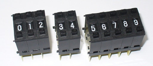
In this article we examine the use of push-wheel/thumbwheel switches with our Arduino systems. Here are some examples sourced from PMD Way:

Thumbwheel switches from PMD Way

For the uninitiated, each switch is one vertical segment and they can be connected together to form various sizes. You can use the buttons to select from digits zero through to nine. There are alternatives available that have a wheel you can move with your thumb instead of the increase/decrease buttons.

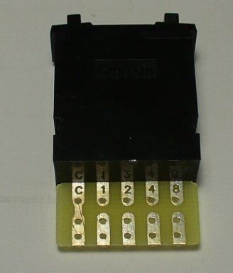
Before the days of fancy user interfaces these switches were quite popular methods for setting numerical data entry. However they are still available today, so let’s see how they work and how we can use them. The switch’s value is made available via binary-coded decimal or straight decimal. Consider the rear of the switch in BCD form:

Thumbwheel switches from PMD Way

We have common on the left, then contacts for 1, 2, 4 and 8. If you apply a small voltage (say 5V) to common, the value of the switch can be measured by adding the values of the contacts that are in the HIGH state. For example, if you select 3 – contacts 1 and 2 will be at the voltage at common. The values between zero and nine can be represented as such:

Thumbwheel switches from PMD Way

By now you should realise that it would be easy to read the value of a switch – and you’re right, it is. We can connect 5V to the common,  the outputs to digital input pins of our Arduino boards, then use digitalRead() to determine the value of each output. In the sketch we use some basic mathematics to convert the BCD value to a decimal number. So let’s do that now.

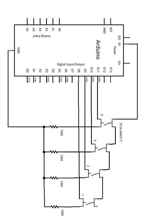
From a hardware perspective, we need to take into account one more thing – the push-wheel switch behaves electrically like four normally-open push buttons. This means we need to use pull-down resistors in order to have a clear difference between high and low states. So the schematic for one switch would be (click image to enlarge):

Thumbwheel switches from PMD Way

Now it is a simple matter to connect the outputs labelled 1, 2, 4, and 8 to (for example) digital pins 8, 9, 10 and 11. Connect 5V to the switch ‘C’ point, and GND to … GND. Next, we need to have a sketch that can read the inputs and convert the BCD output to decimal. Consider the following sketch:

/*
 Uses SAA1064 numerical display shield http://www.gravitech.us/7segmentshield.html
 Uses serial monitor if you don't have the SAA1064 shield
*/
#include "Wire.h"
#define q1 8
#define q2 9
#define q4 10
#define q8 11
void setup()
{
 Serial.begin(9600);
 Wire.begin(); // join i2c bus (address optional for master)
 delay(500);
 pinMode(q1, INPUT); // thumbwheel '1'
 pinMode(q2, INPUT); // thumbwheel '2'
 pinMode(q4, INPUT); // thumbwheel '4'
 pinMode(q8, INPUT); // thumbwheel '8'
}
void dispSAA1064(int Count)
// sends integer 'Count' to Gravitech SAA1064 shield
{
 const int lookup[10] = {
 0x3F,0x06,0x5B,0x4F,0x66,0x6D,0x7D,0x07,0x7F,0x6F };
 int Thousands, Hundreds, Tens, Base;
 Wire.beginTransmission(0x38);
 Wire.write(0);
 Wire.write(B01000111);
 Wire.endTransmission();
 Wire.beginTransmission(0x38);
 Wire.write(1);
 Thousands = Count/1000;
 Hundreds = (Count-(Thousands*1000))/100;
 Tens = (Count-((Thousands*1000)+(Hundreds*100)))/10;
 Base = Count-((Thousands*1000)+(Hundreds*100)+(Tens*10));
 Wire.write(lookup[Base]);
 Wire.write(lookup[Tens]);
 Wire.write(lookup[Hundreds]);
 Wire.write(lookup[Thousands]);
 Wire.endTransmission();
 delay(10);
}
int readSwitch()
{
 int total=0;
 if (digitalRead(q1)==HIGH) { total+=1; }
 if (digitalRead(q2)==HIGH) { total+=2; }
 if (digitalRead(q4)==HIGH) { total+=4; }
 if (digitalRead(q8)==HIGH) { total+=8; }
 return total;
}
void loop()
{
 dispSAA1064(readSwitch()); // sends switch value to display shield
 Serial.println(readSwitch()); // sends switch value to serial monitor box
}

The function readSwitch()  is the key. It calculates the value of the switch by adding the numerical representation of each switch output and returns the total as its result. For this example we used a numerical display shield that is controlled by the NXP SAA1064.

If you don’t have one, that’s ok – the results are also sent to the serial monitor. Now, let’s see it in action:

Ok it doesn’t look like much, but if you need numerical entry it saves a lot of physical space and offers a precise method of entry.

So there you have it. Would you actually use these in a project? For one digit – yes. For four? Probably not – perhaps it would be easier to use a 12-digit keypad. There’s an idea…

Multiple switches

Now we will examine how to read four digits – and not waste all those digital pins in the process. Instead, we will use the Microchip MCP23017 16-bit port expander IC that communicates via the I2C bus. It has sixteen digital input/output pins that we can use to read the status of each switch.

Before moving forward, please note that some assumed knowledge is required for this article – the I2C bus (parts one and two) and the MCP23017.

We first will describe the hardware connections, and then the Arduino sketch. Recall the schematic used for the single switch example:

Thumbwheel switches from PMD Way

When the switch was directly connected to the Arduino, we read the status of each pin to determine the value of the switch. We will do this again, on a larger scale using the MCP23017. Consider the pinout diagram:

Thumbwheel switches from PMD Way

We have 16 pins, which allows four switches to be connected. The commons for each switch still connect to 5V, and each switch contact still has a 10k pull-down resistor to GND. Then we connect the 1,2,4,8 pins of digit one to GPBA0~3; digit two’s 1,2,4,8 to GPA4~7; digit three’s 1,2,4,8 to GPB0~3 and digit four’s 1,2,4,8 to GPB4~7.

Now how do we read the switches? All those wires may cause you to think it is difficult, but the sketch is quite simple. When we read the value of GPBA and B, one byte is returned for each bank, with the most-significant bit first. Each four bits will match the setting of the switch connected to the matching I/O pins.

For example, if we request the data for both IO banks and the switches are set to 1 2 3 4 – bank A will return 0010 0001 and bank B will return 0100 0011. We use some bitshift operations to separate each four bits into a separate variable – which leaves us with the value of each digit.

For example, to separate the value of switch four, we shift the bits from bank B >> 4. This pushes the value of switch three out, and the blank bits on the left become zero. To separate the value for switch three, we use a compound bitwise & – which leaves the value of switch three.

Below is a breakdown of the binary switch values – it shows the raw GPIOA and B byte values, then each digit’s binary value, and decimal value:

Thumbwheel switches from PMD Way

So let’s see the demonstration sketch :

/*
 Example 40a - Read four pushwheel BCD switches via MCP23017, display on SAA1064/4-digit 7-segment LED display
 */
// MCP23017 pins 15~17 to GND, I2C bus address is 0x20
// SAA1064 I2C bus address 0x38
#include "Wire.h"
// for LED digit definitions
int digits[16]={
  63, 6, 91, 79, 102, 109, 125,7, 127, 111, 119, 124, 57, 94, 121, 113};
byte GPIOA, GPIOB, dig1, dig2, dig3, dig4;
void initSAA1064()
{
  //setup 0x38
  Wire.beginTransmission(0x38);
  Wire.write(0);
  Wire.write(B01000111); // 12mA output, no digit blanking
  Wire.endTransmission();
}
void setup()
{
  Serial.begin(9600);
  Wire.begin(); // start up I2C bus
  initSAA1064();
}
void loop()
{
  // read the inputs of bank A
  Wire.beginTransmission(0x20);
  Wire.write(0x12);
  Wire.endTransmission();
  Wire.requestFrom(0x20, 1);
  GPIOA=Wire.read(); // this byte contains the switch data for digits 1 and 2
  // read the inputs of bank B
  Wire.beginTransmission(0x20);
  Wire.write(0x13);
  Wire.endTransmission();
  Wire.requestFrom(0x20, 1);
  GPIOB=Wire.read(); // this byte contains the switch data for digits 3 and 4
  // extract value for each switch
  // dig1 LHS, dig4 RHS
  dig4=GPIOB >> 4;
  dig3=GPIOB & B00001111;
  dig2=GPIOA >> 4;
  dig1=GPIOA & B00001111;
  // send all GPIO and individual switch data to serial monitor
  // for debug and interest's sake
  Serial.print("GPIOA = ");
  Serial.println(GPIOA, BIN);
  Serial.print("GPIOB = ");
  Serial.println(GPIOB, BIN);
  Serial.println();
  Serial.print("digit 1 = ");
  Serial.println(dig1, BIN);
  Serial.print("digit 2 = ");
  Serial.println(dig2, BIN);
  Serial.print("digit 3 = ");
  Serial.println(dig3, BIN);
  Serial.print("digit 4 = ");
  Serial.println(dig4, BIN);
  Serial.println();
  Serial.print("digit 1 = ");
  Serial.println(dig1, DEC);
  Serial.print("digit 2 = ");
  Serial.println(dig2, DEC);
  Serial.print("digit 3 = ");
  Serial.println(dig3, DEC);
  Serial.print("digit 4 = ");
  Serial.println(dig4, DEC);
  Serial.println();
  // send switch value to LED display via SAA1064
  Wire.beginTransmission(0x38);
  Wire.write(1);
  Wire.write(digits[dig4]);
  Wire.write(digits[dig3]);
  Wire.write(digits[dig2]);
  Wire.write(digits[dig1]);
  Wire.endTransmission();
  delay(10);
  delay(1000);
}

And for the non-believers … a video demonstration:

So there you have it. Four digits instead of one, and over the I2C bus conserving Arduino digital I/O pins. Using eight MCP23017s you could read 32 digits at once. Have fun with doing that!

You can order both BCD and decimal switches in various sizes from PMD Way, with free delivery worldwide.

This post brought to you by pmdway.com – everything for makers and electronics enthusiasts, with free delivery worldwide.

To keep up to date with new posts at tronixstuff.com, please subscribe to the mailing list in the box on the right, or follow us on twitter @tronixstuff.

Learn to solder with eevblog’s David L. Jones!

Hello Readers

How is your soldering? Have you always wanted to improve your soldering skills, or never heated an iron in your life and didn’t know where to start? No matter your level of skill you could do a lot worse than review the following video blogs in this article by David L. Jones.

Who? 

[David] shares some of his 20 years experience in the electronics design industry in his unique non-scripted naturally overly enthusiastic and passionate style.
Bullsh!t and political correctness don’t get a look-in.

Dave started out in hobby electronics over 30 years ago and since then has worked in such diverse areas as design engineering, production engineering, test engineering, electro-mechanical engineering, that wacky ISO quality stuff, field service, concept design, underwater acoustics, ceramic sensors, military sonar systems, red tape, endless paperwork trails, environmental testing, embedded firmware and software application design, PCB design (he’s CID certified), power distribution systems, ultra low noise and low power design, high speed digital design, telemetry systems, and too much other stuff he usually doesn’t talk about.

He has been published in various magazines including: Electronic Today International, Electronics Australia, Silicon Chip, Elektor, Everyday Practical Electronics (EPE), Make, and ReNew.

Few people know Dave is also a world renowned expert and author on Internet Dating, a qualified fitness instructor, geocacher, canyoner, and environmentalist.

Regular readers of this website would know that I rarely publish outside material – however the depth and quality of the tutorials make them a must-see for beginners and experienced people alike. Furthermore, if you have the bandwidth they can be viewed in 1080p. And as a fellow Australian I’m proud to support Dave and his efforts. So I hope you can view, enjoy and possibly learn from the following videos:

The first covers the variety of tools you would use:

And the second covers through-hole PCB soldering:

The third covers surface-mount soldering:

Finally, watch the procedure for soldering a tiny SMD IC using the ‘dead bug’ method:

And for something completely different:

If you enjoyed those videos then don’t forget to check out what’s new on Dave’s eevblog website and forum. Videos shown are (C) David L. Jones 2011 and embedded with permission.

As always, thank you for reading and I look forward to your comments and so on. Furthermore, don’t be shy in pointing out errors or places that could use improvement. Please subscribe using one of the methods at the top-right of this web page to receive updates on new posts, follow on twitterfacebook, or join our Google Group.